Identifying Energy Components in Exhaust Ventilation Systems

Exhaust ventilation sytems, whether simple or complex, share common system components, each of which has its own energy loss.
Understanding the energy losses of exhaust ventilation system components is key to designing, evaluating and operating the system for optimum performance without excessive energy. This article identifies the energy components in a typical exhaust ventilation system, allowing a clear accounting for the total system energy requirements.
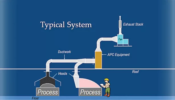
System components common to exhaust ventilation systems are:
- Hood(s) for air entry into the system
- Ducting to transport the air from the hood to its final release point
- Duct fittings such as elbows, branch entries, contractions, expansions, or mechanical devices (such as dampers) used in routing the ducting from the hood to its final release point.
- Air pollution control (APC) equipment, ranging from simple static filters to more sophisticated air cleaning or conditioning equipment trains
- The fan used for moving the air through the hood to its final release point.
So let’s take a look at the energy requirments corresponding to each of the above system components.
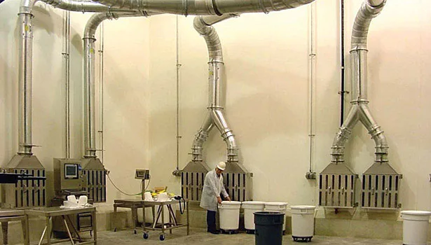
SYSTEM COMPONENT: HOOD
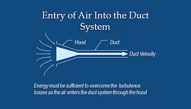
By definition, a hood is a shaped entry through which air enters the exhaust system. There are two corresponding energy components which occur as air enters the exhaust system through a hood.
ACCELERATION ENERGY
This is the energy required to accelerate the air from its natural state through the hood and into the duct to achieve the design velocity for transport through the system. It can be envisioned as the inertia component of an air system similar to the wk2 component of a mechanical drive system. In both cases, either the air or the drive component is considered to be at rest and when started, both have to be accelerated to the full design speed of the system. In an air system, this is referred to as acceleration energy.
For an exhaust system this may mean accelerating the air from rest to a duct velocity of anywhere from 2,000 to 4,500 fpm. And since the start point is when the air is at rest, this energy component is normally counted as one duct velocity pressure. It is measured in inches of water gauge and represents the energy conversion from static to velocity pressure.
Noting that a 2,000 fpm duct velocity corresponds to a duct velocity pressure of 0.25 in. wg and a 4,500 fpm duct velocity corresponds to a duct velocity pressure of 1.26 in. wg, it can be seen that the energy reqired to accelerate the air into the exhaust system can be substantial. And, if this energy requirement is unaccounted for or miscalculated, the system performance will be deficient by the same amount.
HOOD ENTRY LOSS
This is the energy component specific to the hood shape and design. It is the energy necessary to overcome losses due to turbulence or the air changing shape as it enters the exhaust system through the hood.
This energy component is normally represented by a hood entry loss factor and is calculated as a factor x the duct velocity pressure.
For instance, if a particular hood design has a hood entry loss factor of 0.25, then the hood entry loss would be calculated as 0.25 x the duct velocity pressure at the duct design velocity.
Example: Take a hood having a hood entry loss factor of 0.25 which moves air into a duct system having a design velocity of 4,000 fpm. Since a 4,000 fpm duct velocity is equivalent to a duct velocity pressure of 1.0 in. wg, then the hood entry loss would be calculated as 0.25 x VPduct, or (0.25)(1.0 in. wg), which would result in a hood entry loss of 0.25 in. wg. Then when we combine the hood entry loss with the acceleration energy (1 duct vp), the cumulative energy required to move the air from rest through the hood to the duct velocity is the hood entry loss, 0.25 in. wg + the acceleraton energy, 1.0 duct vp, or 1.25 in. wg hood static pressure.
Hood entry loss factors used to calculate the hood loss are derived empirically and are noted in a number of publications.1
HOOD FLOW COEFFICIENT, CE
This is the ratio of the actual flow of air from rest into a hood to the theoretical flow that would result if the energy conversion from static pressure to velocity pressure were 100% efficient. Since hoods always have some inefficiency, the hood Ce will always be 1.0.
Mathematically, the hood flow coefficient is defined as the square root of the ratio of the duct velocity pressure to the hood static pressure, or
Ce = √VPd ÷ SPh2
This means that if the hood static pressure is either known by design or by field measurement, then the hood Ce can be calculated in order to determine the hood flow efficiency. And conversely, if there is a target hood Ce at the system design stage, then it can be used to determine the hood entry loss necessary to achieve the targeted hood Ce.
It follows then that in a system having multiple hoods, if the Ce is determined for each hood, then the overall system efficiency of the movement of air from rest into the system via the hoods can also be determined.
SUMMARY
In summary, the energy components associated with the system hood(s) are combined from the acceleration energy of the air from rest to the duct design velocity and the losses resulting from the air movement due to turbulence and the changing of shape as the air enters the hood. These are normally calculated as factors of the duct design velocity pressure and are collectively referred to as the hood static pressure (SPh) in inches of water gauge. And, when using the hood coefficient of flow, Ce, one can make a determination of the efficiency of airflow from rest into the system.
SYSTEM COMPONENT: DUCTING
Energy losses through ducting are pretty well understood throughout industry and are defined as the energy required to overcome resistance to flow as the air moves through the duct. Being a frictional energy representing resistance to flow, duct losses are normally noted as duct static pressure and are calculated as a factor, or friction coefficient of the duct velocity pressure in inches of water gauge x the total duct section length in feet.
There are a wide number of resources commonly available to determine duct energy loss, including simple duct slide rule type hand calculators, duct friction charts and calculation formulas, all having varying degrees of sophistication, accuracy and allowances for changes in duct materials and roughness.3
Using the Darcy-Weisbach equation for duct pressure loss with a) the Darcy-Weisbach friction coefficient (ƒ) from the Moody Diagram or Colebrook Equation as 0.0186 representing an average duct having an absolute roughness coefficient of 5 x 10⁻⁴ feet, a diameter of 10 in. (0.833 ft) and a resulting relative roughness of 0.0006, b) a given duct length (L) in feet, c) a given duct diameter (dh) in feet, d) a standard airstream density ( ) of 0.075 lbm/ft3, and e) a given duct velocity (v) in feet/minute, then the energy loss through a duct segment can be calculated as follows:
Duct segment pressure loss = ƒ (L/dh) ( ) (v ÷ 1096.2)2
Or, when simpliflied for standard air conditions
Duct segment pressure loss = ƒ (L/dh) (vpduct)
Alternatively, work by Loeffler4 based on the velocity pressure method in lieu of the equivalent foot method used for the Moody Diagram resulted in values to calculate the duct friction loss coefficient, F’d, per foot of duct per the duct vp, as follows:
F´d = aVb5
Qc
Example: 2,000 cfm is flowing through 100 feet of 10 in. diameter duct at 3,667 fpm duct velocity and 0.838 in wg duct velocity pressure.
Using the Darcy-Weisbach formula noted above for calculating duct friction loss with
ƒ = 0.0186
L = 100 ft,
dh = 0.833 ft,
= 0.075 lbm/ft3, and
v = 3667 ft/minute
The duct segment friction loss is calculated to be (0.0186) (100/0.833) (0.075) (3667 ÷ 1096.2)2 = 1.87 in. wg sp.
Using the Loeffler method noted above for calculating duct friction loss with a = 0.0307, b = 0.533, and c = 0.612, the duct segment friction loss is calculated to be (F´d) (duct vp) (duct length), or (0.0233) (0.838) (100) = 1.95 in. wg sp.
Using a typical duct calculator for the same calculation, the duct friction loss is shown to be 2.0 in. wg sp.
For this example, the deviation is about 4% between the Darcy-Weisbach formula and Loeffler, and about 7% overall when the duct calculator is considered. However, since most duct calculators are based on standard sheet metal duct construction and a standard duct roughness, the deviation can be much greater when other duct materials are utilized in the system design.
Due to deviations which result from differing methodologies, materials of construction and airstream characteristics, it is recommended that the system designer utilize a common method for each complete system.
SYSTEM COMPONENT: FITTINGS
Energy losses through duct fittings are normally considered dynamic losses since they occur mainly due to the turbulence and the changing of shape of the air as it moves through the fitting. More specifically, it is the energy required to compensate for turbulence and distortion as the air changes direction and shape while moving through the duct fitting.
Like other system energy losses, duct fitting losses are counted as a static pressure and are calculated as a factor which is specific to the particular fitting x the duct design velocity pressure
For example, elbow: A five-piece elbow with a 2.0 centerline radius has an elbow loss factor of 0.19. If the duct design velocity is 4,000 fpm (duct vp =1.0 in. wg), then elbow energy loss would be 0.19 x 1.0 in. wg = 0.19 in wg sp.6
For example, branch entry: Air enters a main duct through a branch entry. The main duct design velocity is 4,000 fpm (vp=1.0 in wg) and the branch entery angle is 30 degrees with a loss factor of 0.18. Then the branch entry energy loss would be 0.18 x 1.0 in wg = 0.18 in wg sp.
Similar to the hood entry loss, factors used to calculate fitting losses are empricially derived and noted in a number of publications.7
The exception would be mechanical devices, such as dampers, blast gates, abort valves, etc., which normally have their own static pressure loss rating provided by the device supplier.
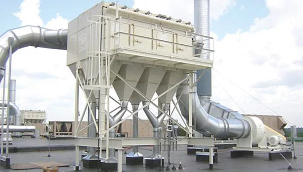
SYSTEM COMPONENT: APC EQUIPMENT
A wide variety of APC equipment is used in exhaust systems, ranging from basic static barrier filters to more sophisticated wet scrubbers, dry media collectors, thermal destruction units, etc. Each is designed and employed for its own specific purpose with systems often employing two or more types of equipment in series for progressive air cleaning or conditioning.
The energy losses represented by these types of equipment can either be fixed or variable. An example of a fixed loss would be a venturi scrubber or cyclone designed to operate at a specific flow rate against a corresponding specific static pressure loss. An example of a variable loss would be a dry media collector, which has a variable flow and static pressure loss corresponding to the contaminant loading on the media.
In all cases, the equipment supplier should be consulted and advise the fixed or variable static pressure loss required for the APC equipment selected for use. Additionally, the equipment supplier should be consulted for any adaptations of the equipment to the specific application, which would result in optimum energy efficiency and minimum energy loss.
SYSTEM COMPONENT: EXHAUST FAN
There are two types of energy losses commonly found in fan applications. The first is the energy loss through the fan itself, which cannot be measured directly and which is already accounted for by the fan manufacturer in the fan capacity ratings. The second is the energy loss which may or may not occur due to the duct system configuration at the fan inlet or outlet. This second energy loss is commonly referred to as fan system effects.
Fan system effects occur when the air entering or exiting the fan does so in a way that it either restricts or distorts the air from properly entering or exiting the fan to the extent that the fan performance is changed noticably.
The Air Movement and Control Association (AMCA) has done considerable empricial research in this area and has published Fans and Systems, Publication 201-02, which provides guidleines and factors for calculating the energy losses corresponding to specific inlet or outlet duct fittings.8
Like other system components, these losses are counted as static pressure and are calculated as a factor which is specific to the individual fitting x the fan inlet or outlet velocity pressure.
SUMMARY: SYSTEM ENERGY COMPONENTS
The energy components common to exhaust ventilaton systems are:
Acceleration energy + hood entry loss + duct friction loss + fittings dynamic loss + air pollution control equipment loss + fan system effects loss = total system energy required.
Of these, the most commonly missed or misunderstood energy components are acceleration, hood entry and fan system effects. Unfortunately, these are often compensated by excessive system design safety factors which results in overdesigned systems operating at low efficiencies — often evidenced by fan dampers with high turndowns.
While it is prudent to allow for a system design safety factor, properly identifying system energy components and computing accurate calculations for each will allow a reasonable factor to be applied to a well-defined system and result in the optimum system energy efficiency.
Looking for a reprint of this article?
From high-res PDFs to custom plaques, order your copy today!


