How BIM can improve your ductwork fabrication efforts
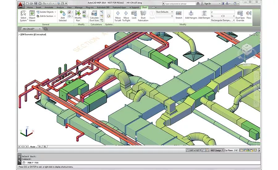
The ongoing BIM revolution is transforming how buildings are constructed. And that’s true at every level, from the initial architectural drawings right down to the design and fabrication of metal components like ductwork.
BIM, which stands for building information modeling, isn’t software. Lots of people seem to think that just because they use computer-aided drafting programs, it means they’re up-to-date with BIM. But it’s so much more than just “computer-based 3-D modeling.” After all, “a drawing” isn’t the same as “modeling.” Instead, BIM is part of the ongoing trend toward creating comprehensive, robust data systems that put information to work instead of just storing it, in much the same way many people are wearing personal fitness tracking devices these days. It’s about making data useful as much as it is about building 3-D models for rendering.
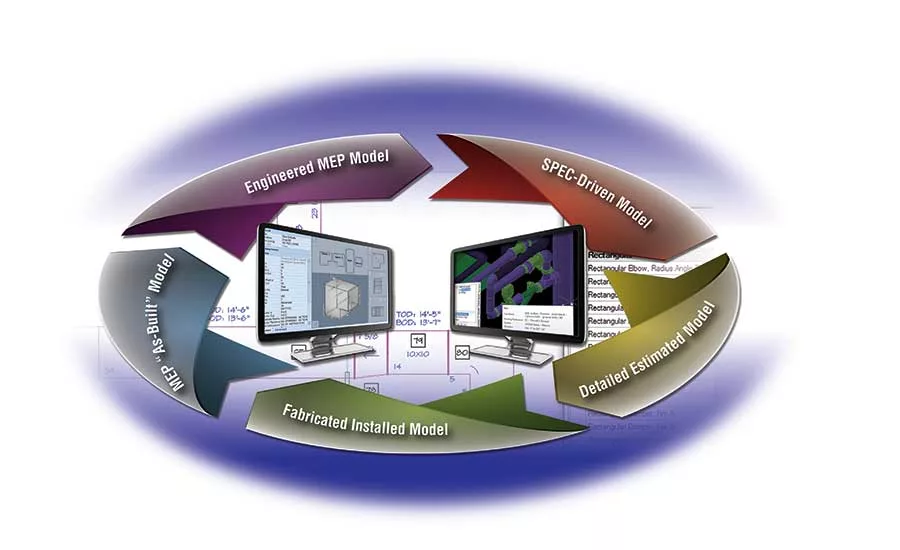
By building information-rich, responsive models, you integrate design with ductwork fabrication into a single workflow that automatically adjusts when it gets new information. Removing the barrier between the drafting table and the sheet metal forming cutting floor strengthens the entire fabrication process, taking each sector out of its individual silo to create a unified operation that’s much more powerful and lets you get more done.
The thing about construction, and especially sheet metal works, is that in many ways it’s still tied to traditional ways. While pen and paper drafting have long since gone away, design — even using powerful drafting programs like Autodesk’s AutoCAD MEP — is generally practiced in isolation.
Avoiding errors
The design sheets are sent to the floor for nesting and cutting, only to discover halfway through that it’s been incorrectly drawn or mislabeled, that it doesn’t conform to the right specifications from the Sheet Metal and Air-Conditioning Contractors’ National Association or the Spiral Duct Manufacturers Association, or simply that something has been neglected.
So it gets sent back up to be redrawn and then re-nested and recut. That takes time, and costs money. It makes the entire job less profitable — and frustrating.
But it doesn’t have to be that way.
Using a BIM system to organize ductwork fabrication would save everyone a lot of time and frustration from the very beginning of the job by creating a unified data environment in which all shop specifications are pre-implemented, data is applied to CAD drawings from the very beginning, and nesting and labeling is automated to ease the cutting process. By automating data transfer and specification loading, you generate drawings at the design stage that are already primed for fabrication — without time wasted in the coordination and fabrication stages.
And by integrating data into the model, you can build self-correcting designs; if a job specification changes, the new information simply needs to be updated in the system — and the design will automatically adjust to meet the new standards. That saves you time and money during the fabrication and installation process by allowing you to more effectively be proactive instead of reactive; even if re-fabrication is needed to meet the on-the-ground situation, time won’t need to be spent recalculating and redrawing the entire duct system.
Simplification
BIM-oriented software integration can be used to simplify your projects and reduce your overall working time by minimizing input and enabling automation.
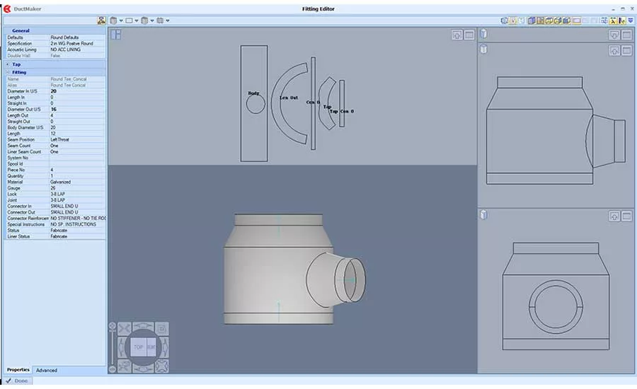
Designing an intelligent system to coordinate your data is important, because you want to automate your specifications. What that means in practice is that you can adjust your specifications without having to remodel the entire component. If, for example, you’re designing a reducing, round-T conical and need to adjust the outlet diameter of the piece, you want the software to automatically ensure that the length of the reducer is always consistent with your desired specification, with no math or additional work required on the part of the designer to make sure it conforms to industry standards.
The component, the round-T conical, is loaded with a ton of information. It knows its dimensions. It knows what material it’s going to be made of. It knows its gauge, locks, joints and connectors. It knows whether or not it will need any additional reinforcement to support the air pressure that it is being designed for. And most importantly for our purposes here, it knows that it needs to conform to SPIDA specifications, used throughout North America, or any other set of shop rules you want to apply to it.
What this means is that you can always ensure, with the use of the right intelligent data system, that the fitting does conform, without requiring any additional design work to be done. Even after the component has been laid out, it can be later modified and the data will automatically adjust accordingly.
BIM for duct manufacturing means that you need to make sure you’ve got the right data in the right places. Industry-standard CAD programs like Autodesk’s AutoCAD MEP and Revit don’t automatically import or support manufacturer defaults, and so depend on manual coordination to turn them into true fabricate-able sections.
Integration
Integrating programs into a fully BIM-optimized workflow, then, is a matter of building systems of automation to remove manual coordination and automatically pump out fully developed fabrication layouts, converting a dumb model to the appropriate standards.
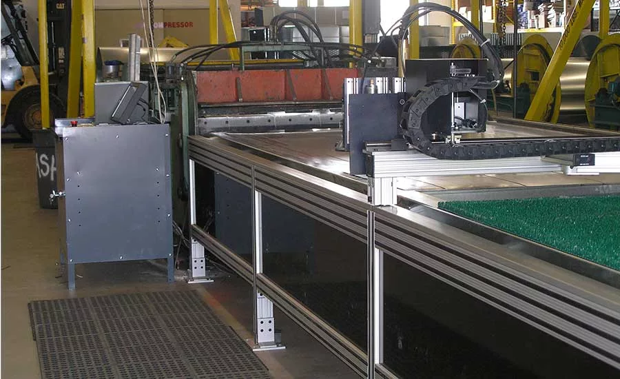
At that point, you move from CAD into computer-aided manufacturing, loading intelligent files into a CAM program that can take them and automate the nesting process to ready the sheets for cutting and assembly.
Using a single file containing all the information you need to fabricate a project can save you and your shop considerable amounts of time and money. You profoundly reduce the amount of time needed to review and manage the dozens of files and documents that would otherwise be required to fully fabricate a complete set of ductwork. A completely BIM-oriented workflow creates a fully responsive model that can be easily tweaked without requiring hours of work, and essentially prepares itself for final manufacture and installation.
This is the power of bringing design and fabrication together: designs that meet the needs of the fabricators on the ground because they exist in a common data environment. This reduces inefficiencies, prevents costly last-minute reworking, and ensures happier client outcomes.
This article and its images were supplied by EastCoast CAD/CAM. For reprints of this article, contact Jill DeVries at (248) 244-1726 or email devriesj@bnpmedia.com.
Looking for a reprint of this article?
From high-res PDFs to custom plaques, order your copy today!