In fact, a study prepared for the U.S. Environmental Protection Agency (EPA) in consideration of changing Energy Star® labeling revealed that 74 percent of central air conditioners and heat pumps have an improper refrigerant charge and 70 percent have airflow lower than 350 cubic feet per minute per ton (cfm/ton).
That means seven out of 10 systems installed today have problems that directly compromise their capacity and efficiency.
If we don't change the way we install and service air conditioning equipment, problems that plague our industry today will not improve. Some will grow even worse. To put it simply, without a change in our actions, the switch to higher SEER levels will just help us waste energy more efficiently.
THE EFFICIENCY CONUNDRUM
History does repeat itself. As field technicians, we have somehow forgotten, or maybe never learned, the delicate balance between airflow, refrigerant charge, cooling capacity, and efficiency. Even if some of us are aware of this dynamic challenge, it seems we have done little to address the true problems that continue to plague our industry.We really shouldn't throw the blame back at the manufacturers. The equipment operates as it was engineered to when the application, the airflow, and the refrigerant charge are all correct.
Oddly enough, we address the problem of record energy consumption with a mandatory increase in efficiency. Is efficiency really the problem, or is it the fact that seven out of 10 units installed today were never commissioned (that is, checked out) properly?
Only two things can be adjusted on a standard residential system: airflow and refrigerant charge. Airflow is critical to the proper operation and capacity of all air conditioning systems. If the airflow is compromised in any way, the equipment cannot achieve its rated capacity.
Air conditioners remove both heat and humidity in a specific ratio (the latent-sensible split), which is critical to achieve comfort. Usually 72-78 percent of the rated capacity removes heat and balances the humidity. Systems with low airflow have good humidity removal but need to run longer to reduce the temperature. Low airflow lowers the sensible capacity. Systems with high airflow remove the heat but not the humidity, leaving the dwelling feeling cold and clammy.
All 13 SEER equipment manufactured today will operate to its designed capacity and efficiency only if the airflow and the refrigerant charge are correct. Anything but the correct charge and correct airflow will directly and negatively affect the capacity and efficiency of the equipment.
The problems that will plague 13 SEER systems are the same as those that have plagued 10, 8, and even 6 SEER equipment. Improper airflow and refrigerant charge lead to decreased comfort, low capacity, excessive electrical consumption, and shortened equipment life, with a higher rate of equipment failure.
Removing humidity is the key to cooling season comfort in most climates. While a few people may argue that you can have full capacity with high airflow (and in some cases even exceed the rated capacity), it's important to remember that it's done at the cost of humidity removal and, ultimately, comfort. If the latent-sensible split is not correct and not enough humidity is removed, your customer will lower the thermostat setting, thereby increasing the runtime.
On the other hand, a system operating with low airflow cannot and will not achieve its rated sensible capacity, and will have excessive runtime to reach the desired thermostat setting if it reaches it at all during peak demand periods.
LET'S MAKE SOME CORRECTIONS
If we really want to take unnecessary load off the power grid, the key is to cycle the equipment off during peak load periods. Systems that operate properly will remove more humidity, allowing for higher thermostat settings that still fall within the cooling season comfort zone.Additionally, systems that operate at their peak capacity will produce the maximum capacity per watt of electricity used. If 70-plus percent of systems have improper charge and airflow, 70-plus percent are operating with substantially lower-than-designed efficiency. (Keep in mind that we haven't even addressed the air delivery system yet. Factor in duct leakage, heat gain, and other losses, and our operating efficiencies plummet.)
So what do we need to do? Even a 23 SEER piece of equipment won't correct the airflow and charge problems.
Correct the airflow. First and foremost, the airflow at the equipment must be correct across the evaporator coil. Airflow should be set at a nominal 400 cfm/ton unless otherwise specified by the manufacturer. Many methods will get the airflow in the ballpark, and for the most part, unless you are benchmarking the equipment (calculating the actual capacity), any of these methods will prove accurate enough.
Why aren't these methods used? There are several reasons, but the main one is time. Measuring air quantity can take considerable time. Couple that with the fact that after the airflow is adjusted it needs to be remeasured, and many technicians don't think they will see the benefits. Equipment seems to operate properly without measuring and setting the proper airflow. Temperature drop across the coil at 20°F has seemed to work well for the past umpteen years. When done, cool air is coming from the ducts.
But to operate at the designed capacity, the system's airflow has to be set to the manufacturer's design criteria at the evaporator coil. Temperature drop across a coil varies with the latent load: the more humidity, the more cooling energy goes toward converting water vapor to water. Temperature drop across the evaporator can easily fall within 16° to 24°F. Therefore, it's imperative to set the airflow to the proper range. Do not rely on the temperature drop across the coil to verify system performance.
The conditions of air entering the coil don't normally affect the coil's design temperature difference (the difference in temperature between the return air and the coil surface). They will, however, affect the temperature of air leaving the coil. As the humidity of the air entering the coil goes up, the temperature drop across the coil decreases.
If the system uses a fixed-type metering device, the evaporator superheat will increase proportionally with an increase in humidity. Systems using a thermal expansion valve (TXV) under excessive heat and humidity (high load) conditions see an increase in suction pressure and temperature, raising the temperature of the evaporator above the design temperature difference of the coil in an attempt to maintain the designed superheat and control the load.
While this is not common with air-type evaporators, it can and it does happen. Under these conditions, the equipment would be operating far outside of its design conditions.
HOW TO CORRECT THE AIRFLOW
The most common and easiest way to verify and set airflow is to use one of the following means:
The airflow must first be set according to the equipment design and not to the register delivery. While the design of the duct system is imperative for proper air distribution to the conditioned space, air measurements are only to be measured at the appliance for the equipment commissioning procedure. Due to leakage inherent with all ducting systems, airflow cannot be measured at the registers to verify correct airflow across an evaporator coil or heat exchanger.
If the airflow is properly set at the appliance and the equipment operation is verified to be correct, but the system still cannot heat or cool the home, the problem isn't with the operation of the equipment. The ducting system needs to be evaluated for excessive leakage, proper sizing, and proper design. A review of the heat load calculation also may be required to verify that the equipment selection was correct if the system will not perform properly.
Don't adjust the airflow to change system-operating characteristics like air noise or low register airflow; decreased capacity and/or system damage could result.
Although 400 cfm/ton goes across the evaporator coil, only about 350 cfm/ton is delivered out of the registers. Approximately 50 cfm/ton is usually lost due to leakage from poorly sealed ducts on most systems. This is a serious problem that should be corrected whenever possible. Duct sealing and insulating are an important part of the overall equation.
Note: When you are making any airflow/quantity measurements for cooling or heating, all dampers must be in their normal operating position, all equipment panels and doors must be in place. Many manufacturers have a removable base pan for bottom return. If a side return is used, make sure the bottom return is properly sealed, the return airdrop is securely fastened, and a proper sealant (such as mastic) is used to seal the connections. A digital manometer can be used to check for pressure differential between the bottom side of the base pan and the surrounding air.
The fan must be operating at the speed at which it will be operating when the system is cooling.
The condensing unit should not be in operation during the measurement process; moisture that accumulates on the evaporator coil will significantly affect the pressure differential readings. It's usually easiest to pull the service disconnect for the condensing unit, locking out the condenser. This will allow the system to operate in the cooling mode without conditioning the air during the system's airside commissioning.
Note: It's imperative that the ducting attached to the appliance and the base pan (if side return is used) is sealed. Air leaks will significantly alter the actual reading from this method if the leaks are located upstream of where the measurements are made. If done carefully, the measurement error will be less than 2 percent. Even changes in yaw and the pitch of the probe head in the duct (as much as 10 percent) will result in less than 1 percent error in the measurement, making the mini-vane an ideal probe for field air measurement.
Note: While this measurement is accurate enough for setting up equipment, it is not accurate enough to make a field measurement of system capacity.
Note: It is imperative that the ducting be attached to the appliance, and the base pan (if side returned is used) is sealed. Air leaks upstream of where the measurements are made will significantly alter the actual reading obtained with this method.
To verify cfm in a natural gas furnace, let the furnace run for 10 minutes (or until the stack temperature stabilizes), allowing the appliance to reach steady-state efficiency. Using a combustion analyzer, determine the steady-state operating efficiency of the appliance and multiply it times the Btuh input to get the output Btuh of the furnace. (Remember, if the heat is not going up the stack, it is going into the house.)
If a combustion analyzer is not available, the manufacturer's literature could be used to determine the output Btuh of the furnace, as long as the manifold pressure is correctly set and the Btu content of the fuel used is consistent. (The manufacturer's tag is a good place to look for this.)
Note: Do not use efficiency information from the yellow Energy Guide label. This is Annual Fuel Utilization Efficiency (AFUE), and it takes into account efficiency losses at startup of the equipment.
Measure the temperature rise across the heat exchanger. It's important to be out of the line of sight of the heat exchanger when you're making these measurements; the temperature probe can be affected by radiant heat from the heat exchanger.
If the furnace has a bypass humidifier, make sure the bypass is closed. Then enter your results into the natural gas sensible heat formula. This is an approximate method. The heat content of natural gas varies across the United States and even from the same meter from hour to hour, and there is additional heat added from the blower motor. Heat added by the motor can be as much as 300 W, or 1,024 Btu. This will give you an approximate cfm, although it will be very close to the actual if the measurements are made accurately and the heat content of the natural gas is near 1,000 Btu/cubic foot.
The procedure is the same for an electric furnace. Allow the appliance to operate until the temperature rise stabilizes. Measure the temperature rise again out of the line of sight of the electric heater, along with the incoming volts and current draw in amps to the electric strip heaters.
For fuel oil, the procedure involves verifying the nozzle size and correct fuel pressure. After the nozzle size in gallons per minute (gpm) is known and the fuel pressure is set, measure the combustion efficiency with a stable stack temperature, and record the temperature rise across the heat exchanger.
After you set airflow, you must verify the system's refrigerant charge. A standard condenser comes with enough refrigerant charge to operate with a 25-foot refrigerant line set and a matched evaporator coil. However, even if the installation is standard, you may need to adjust the charge.
GAUGING YOUR PERFORMANCE
It bears repeating: 74 percent of central air conditioners and heat pumps have an improper refrigerant charge. Systems have reverted back to the TXV and manufacturers now require tighter tolerances for the refrigerant charge (many require ±3° of subcooling). We need to review the basics.A standard R-22 high-side gauge has a range of 0-500 psi. R-410A/R-22 high-side gauges range from 0-800. The standard gauge has an accuracy of ±2 percent of the full-scale reading, or ±10-16 psi. The R-410A set with the 1 percent accuracy is ±8 psi. Remember, these gauges are brand new, but still are not guaranteed to be accurate unless you take them to a gauge house for calibration after purchase. You also need to factor in errors that are created if your pressure isn't read correctly, and the resulting error in the temperature reading.
Additionally, consider that a pressure-temperature (P-T) chart gives you 5-psi increments above 150 psi; information must be extrapolated from the chart.
Finally, consider that gauges lose accuracy outside of the altitude and barometric pressure they were calibrated for, and any bumps can ruin the calibration of any mechanical gauge.
Start adding these variables together, and let alone any inherent inaccuracy in the temperature measurement, getting the charge correct with traditional measures is improbable, if not nearly impossible.
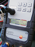
Unlike traditional gauge sets, digital gauges (like the Testo 523) have dual pressure transducers that are accurate over the full range of working pressure and temperature measurements. From -14.7 to 725 psi, the sensors display with 0.1-psi resolution. The high- and low-side sensors are identical, allowing accurate pressure measurement over the full range on either side. The 35 onboard P-T charts (can hold three additional user-variable charts) provide detail and accuracy. Unlike traditional charts, no interpolation of the P-T relationship is required.
In order to properly charge a refrigeration system, you also need to verify the type of metering device. Different types of metering devices require different measurements. Some manufacturers have special charging requirements.
In general, physics is physics. Technicians will find that almost all air conditioning systems operate with similar characteristics. The physical and chemical laws that govern science do not change. Energy transfer is a function of time, temperature difference, and turbulence (mixing). Since the time and turbulence are a factor of the airflow (set at a nominal 400 cfm/ton), the operating characteristics will be almost identical across the board.

STATES OF REFRIGERANT
Refrigerant has three states in the refrigeration system:1. Saturated (a mixture of liquid and vapor).
2.Superheated (refrigerant vapor with measurable heat added above its saturation temperature).
3. Subcooled (refrigerant liquid at a temperature below the saturation temperature).
Superheat is measured to make sure that the evaporator is operating at its maximum efficiency, and that liquid refrigerant is not going to enter the compressor. With a fixed metering device, superheat will vary with the load and the ambient conditions. With a TXV, the superheat will remain constant (provided the load is not way above or below the operating conditions).
Subcooling is measured to make sure the expansion device has a solid column of liquid fed to it, ensuring that the metering device will be able to control the load at its peak efficiency. With a TXV, the subcooling will follow a manufacturer's curve based on a given set of operating conditions, or proper equipment subcooling will be listed on the manufacturer's equipment tag. With a fixed metering device, the subcooling is not often measured. The system is charged from a superheat curve. Subcooling will be a function of the refrigerant in the evaporator.
When charging a refrigeration system, use a charging calculator or the manufacturer's charging chart to ensure the correct charge. One manufacturer's chart will work with any brand of equipment provided the same style metering device and the same nominal airflow is common between them. Manufacturers can have different subcooling requirements for different types of condensers, but 8-10° subcooling is normally the standard. Many of the newer 13-15 SEER systems will require subcooling in the 11-15° range for proper operation, so consult the manufacturer's label or contact the manufacturer if the proper charge requirements are in question.
STEPS FOR PROPER CHARGING
1. Inspect filters, evaporator coils, condenser coils, and blower for dirt; clean if needed. If the condenser is washed, let it dry before charging.2. Make sure the evaporator airflow is correct (400 cfm per ton for air conditioners and 450 cfm per ton for heat pumps).
3. Determine the type of refrigerant.
4. Determine the type of metering device.
5. Measure indoor and outdoor ambient air conditions (wetbulb and drybulb).
6. Determine proper superheat or subcooling. (Use manufacturer's chart if available.)
7. Attach a recording manifold gauge set to the service valves.
8. Attach temperature probe (to the suction line for superheat measurement, to the liquid line for subcooling measurement).
9. Verify refrigerant selection in manifold.
10. Charge directly by superheat or subcooling.
11. Verify that system pressures and saturation temperatures are within the manufacturer's design criteria.
With digital gauges, refrigeration systems can be charged directly by superheat or subcooling. Remember, you should never charge by pressure or temperature. It is the superheat or subcooling that determines the proper charge. Once the airflow is correct, the evaporator will operate as designed and charging the system is a breeze.
Correct airflow and refrigerant charge are the keys to successful system operation. Without addressing these areas, poor performance and poor efficiency will continue to plague our industry. With proper instrumentation, airflow can be measured and set in a matter of minutes, and the refrigerant charge can be verified in all cases.
When it comes to your bottom line, the investment you make in instrumentation is much smaller than the costs associated with callbacks, dissatisfied customers, and wasted utilities. Doing it right once is always cheaper than doing it twice (or more). Doing it digitally just makes sense.
Sidebar: Low Ambient Conditions
A common problem for service technicians is charging refrigeration equipment during low ambient conditions. With a digital a/c and refrigeration analyzer and an accurate wetbulb thermometer/hygrometer, it is possible and easy to accurately charge air conditioning systems at ambient temperatures as low as 55°F outdoor air, with indoor wetbulb temperatures as low as 50°.Below 70° indoor air temperature, the wetbulb temperature must be used; wetbulb takes into account the total heat in the air. There must be enough heat (latent and sensible) in the air to evaporate the refrigerant in the evaporator coil at a rate equal to the rate it is being fed into the evaporator coil, or the evaporator will become flooded (overfilled with liquid refrigerant).
It's imperative that cap tube systems are properly charged. A few ounces of refrigerant can drastically affect the operational characteristics of an evaporator using a capillary tube or other fixed-type metering device.
Publication date: 06/26/2006

Report Abusive Comment