How to Do Filter Differential Pressure Alarming the Right Way
Using a fixed alarm threshold for filter pressure alarms on variable air volume system will result in inaccurate readings
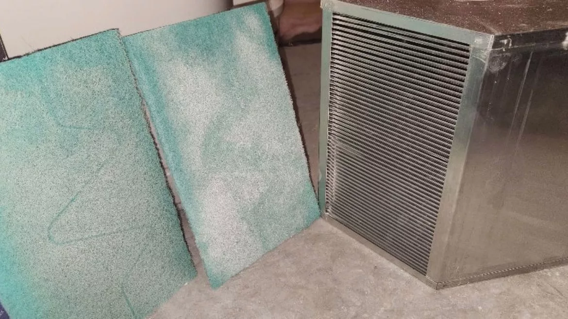
(Courtesy of Full Throttle Furnace & Duct Cleaning Inc.)
BAS monitoring of the differential pressure across a filter within an air system is commonplace. The differential pressure across the filter will increase as the filter gets loaded. If it gets too high, an alarm can be generated on the BAS which will inform building operators it is time to replace the filter. This approach is commonly viewed as superior compared to changing filters at set time intervals. Unfortunately, it is rarely, if ever, implemented correctly.
Filter Loading, Differential Pressure and Airflow
The differential pressure drop across a filter is dependent on both how loaded (i.e. dirty) the filter is, as well as the airflow across it. Figure 1 below shows the relationship between these three variables. As airflow increases, the differential pressure drop across a filter will increase proportionally to the flow rate squared. As the filter loads up, the relationship between pressure drop and airflow becomes steeper. The dependency of pressure drop on airflow is often neglected when developing alarming thresholds for filter changes.
 Figure 1: Filter pressure drop dependency on airflow and filter loading.
It is common for a BAS dirty filter alarm to be generated when some fixed alarm threshold is reached. 1 or 1.5 inch w.g. are common thresholds utilized. This should be the pressure drop across a fully loaded filter at design (maximum) airflow. There are two issues with this approach:
- This approach will often not generate an alarm in variable air volume systems operating at less than design airflow, even with an excessively loaded filter (see Figure 2).
- This approach may work for constant volume systems, but rarely is any effort put into finding the correct setting for this alarm threshold. The common thresholds of 1 and 1.5 inch w.g. come from a typical filter manufacturer’s literature for the final resistance experienced on a fully loaded filter. However, that published pressure drop is for a specific airflow. If the design airflow of the system differs from the value published by the filter manufacturer, then some analysis needs to be performed for what the correct threshold should be at the airflow the system is designed to operate at.
 Figure 2: The ineffectiveness of a fixed filter alarm threshold in variable air volume systems.
Differential Pressure Switches vs Differential Pressure Transducers
There are two common approaches for BAS monitoring of the differential pressure across a filter. A differential pressure switch is a binary input device for a BAS. Pressure reference ports are placed before and after the filter. The switch sends a “normal” signal when the differential pressure is below its setting.
If differential pressure across the filter exceeds the switch’s setting, the switch will trigger and an “off normal” signal will be sent to the BAS. Commonly, the BAS will monitor that binary input, and if it remains “off normal” for a set duration (e.g. 30 minutes), a latching alarm will be generated to inform the building operator it is time for a filter change. This switch’s trigger setting is set on the switch itself, typically by the temperature controls contractor during their point-to-point checkout. Since the switch’s setting (i.e. the alarm threshold) is fixed, such a device is clearly inappropriate for variable air volume systems. It will rarely, if ever, trigger, assuming an appropriate alarm threshold is utilized. Yet, I see these differential pressure switches specified time and time again in variable air volume systems. When the building operators never get an alarm and eventually find a woolly mammoth of a filter, they tend to quickly revert to changing the filters on a regular time interval.
A differential pressure transducer is an analog input device for a BAS. Pressure reference ports again are placed before and after the filter. These transducers provide a reading to the BAS across a range (e.g. 0.0-2.5 inches w.g). The real time differential pressure reading across the filter is then displayed on the BAS graphic for the system. Clearly the added sophistication of such an analog input could allow for more appropriate alarming, but usually a fixed alarm threshold is still used for the BAS alarm. So, what would more appropriate alarming look like?
 Figure 3: Excerpt from ASHRAE Guideline 361 for filter differential pressure alarm logic for a multizone, variable air volume AHU.
Resetting Alarm Thresholds
ASHRAE Guideline 361 presents a resetting alarm threshold for variable air volume systems. See Figure 3 for a snip of how they present it. Figure 4 is my graphical representation of what ASHRAE 36 presents. Notice the exponent used in the calculation is not 2, rather 1.4. This allows a bit of a gap between the alarm threshold and expected pressure drops experienced as a filter approaches its fully loaded state during part load scenarios. This will avoid nuisance trips at lower airflows due to slight inaccuracies in the differential pressure transducer’s readings. Similarly, the flat fixed threshold of 0.05 in w.g. at lower airflows is used to again prevent premature alarming due to accepted levels of sensor inaccuracy. To implement this approach, supply airflow readings are needed. However, supply fan speed (though less accurate in AHUs with modulating downstream dampers) is allowed by ASHRAE Guideline 36.
 Figure 4: Graphical representation of ASHRAE Guideline 36’s resetting alarm threshold logic for filter differential pressure.
Conclusion
Certainly, implementing ASHRAE 36’s resetting alarm threshold brings another level of complexity to a relatively less critical function of a BAS. Often this level of complexity is more than a lot of project teams can handle, and it is probably not worth pursuing. I certainly don’t make a practice of recommending it to project teams. However, if you are going to do anything in life, I believe you better do it right.
I urge readers to first question if a project really needs filter pressure alarming at all. In my experience, only a small minority of building operators are really changing filters via this “on-demand” practice in lieu of set time intervals. I have several clients where the managers in the facility operations staff are adamant they change filters only when the BAS tells them to, but conversations with their field personnel tell me they are actually still using fixed intervals.
For when such alarms will truly serve a purpose for a facility operations staff, then it has to be done the right way. If a fixed alarm threshold for filter pressure alarms is used on a constant volume system, make sure the appropriate value is used by analyzing the filter manufacturer’s performance data. If the ASHRAE 36 approach is to be used in variable air volume systems, the same effort of consulting the filter manufacture’s literature would need to be done to determine the variable DP100, defined in Figure 3.
The major takeaway for this article is that using a fixed alarm threshold for filter pressure alarms on variable air volume system is pointless. It will not accurately predict when a filter reaches its design loading. An analog differential pressure transducer is still a valuable bit of information even if no alarm is tied to it. But placing a binary, differential pressure switch across a filter in a variable air volume system is a waste of money.
1 ASHRAE Guideline 36-2021, High-Performance Sequences of Operation for HVAC Systems.
Looking for a reprint of this article?
From high-res PDFs to custom plaques, order your copy today!