Using MAU Cooling Coils as Dry Coolers, Part III
Three-part makeup air unit case study saga offers valuable lessons
Images courtesy of Questions & Solutions Engineering
This is the third and final installment in the series on using makeup air unit (MAU) cooling coils as dry coolers. Part I introduced the concept and provided a case study with an air-cooled chiller and a chilled water system which utilized glycol. Part II provided a second case study with a water-cooled chiller and a primary-only chilled water system, where the MAU cooling was provided by a dedicated glycol chilled water loop and an accompanying chilled water-to-glycol chilled water heat exchanger (HX). This installment will provide a third case study with a similar arrangement to Part II, but whose slight differences provided some additional opportunity to improve the performance of such a Dry Cooler Mode of operation.


Building No. 3
The final case study in this series had the system configuration depicted in Figure 1. The condenser water system had a remote sump, located in the conditioned mechanical room. When the system was disabled, all water drained to the remote sump, which prevented the need for seasonal draining of the condenser water system as was needed in Part II’s case study.
The primary/secondary chilled water system does not contain glycol. The only portion of the system that would be exposed to freezing temperatures would be that of the cooling coil located in the MAU. To protect that coil but avoid the costs of adding glycol to the entire chilled water system, a separate glycol chilled water loop is present. This glycol loop is dedicated to the MAU cooling coil and is served by the chilled water system via a plate and frame heat exchanger (HX-1).
Our firm was contracted to perform a retro-commissioning study of the building with the focus on finding energy savings along with addressing some known performance issues. The initial control sequence for the building included a Dry Cooler Mode to provide chilled water during colder ambient conditions, though its implementation was energy intensive. The strategy included running the glycol chilled water pump continuously, regardless of outdoor air temperature. The HX-1 control valve also remained 100% open at all times, regardless of outdoor air temperature. The chiller and condenser water system disabled at outdoor air temperatures below 45°F, but the lead secondary chilled water pump remains enabled. This strategy allowed for the MAU cooling coil to naturally transition to a dry cooler when the chiller was disabled. When the chiller was enabled though, the system was subcooling the incoming outdoor air to the MAU excessively, and often when not needed. This resulted in the need to keep the hot water system enabled continuously, with its only summer-time load being reheat at the MAU.
To illustrate the energy waste associated with this approach, imagine outdoor air conditions at 68°F dry bulb, 57°F dewpoint. The MAU could land at neutral 70°F supply air (accounting for fan heat gain) and 57°F dewpoint without running the cooling coil or heating coil and their associated glycol pumps. If the control sequence was configured to not sub cool and then reheat the air in such a scenario, substantial thermal energy savings could be realized at the MAU, but also the hot water system would not need to be running, the secondary chilled water pumps would be dialed back due to the HX-1 control valve being closed, and the glycol chilled water and glycol hot water pumps serving the MAU could be disabled. There were even more energy savings opportunities though. Those two glycol pumps were initially set to run at 60 hz despite having a variable frequency drive on them, as balancing had been “value engineered” out of project when the building was constructed. Based on the design documents, we believed the pumps were well oversized for their application, a theory proved true once we brought a TAB professional out to the building.
In addition to the energy waste described above, the current approach also had performance issues in the winter when the cooling coil was being used as a dry cooler. We had heard the wintertime Dry Cooler Mode “couldn’t keep up” with the cooling demand of the building on the colder days of the year. This made no sense, considering the cooling capacity of such a dry cooler goes up, and the building cooling requirements go down, as outdoor air temperature drops (see Figure 2). Observation of the system in the winter quickly identified the issue. The chilled water (non-glycol side) was freezing within HX-1 when the glycol chilled water temperature got too cold. This prevented any chilled water flow through the HX-1, which was the building’s only source of cooling in the winter. This is the same scenario that was experienced in Building 2’s case study presented last month.


Heat Exchanger Control Theory
Before I describe the improved sequence of operation we implemented, I want to first visit some fundamentals on controlling a HX. In a HX, the primary side is where the source of thermal energy is coming from. The secondary side is the load. The secondary side’s load dictates how much heat transfer needs to occur at the HX. The primary flow needs to be manipulated to meet the secondary side’s load requirement.
So, if the HX shown in Figure 3 is the chilled water-to-glycol chilled water heat exchanger serving the MAU, then we could manipulate the primary flow by use of the modulating control valve to meet the cooling requirements of the MAU during summertime cooling operation (i.e. Chiller Mode).
If the HX was being utilized in the winter (Dry Cooler Mode) however, the primary and secondary sides of the HX swap. Now the chilled water system is the load (secondary side), and the glycol chilled water is the source (primary side). To modulate the primary, source water flow, the only controlled device we have at our disposal is the pump. In Building #2’s case study discussed last month, we manipulated that flow by cycling the glycol chilled water pump on and off when the leaving chilled water out of the HX got too cold. In Building #3 discussed in this article, we have an added modulation capability for better control given the presence of the glycol chilled water pump’s VFD.
Improved Sequence of Operation
Taking all the items described above into consideration. We landed with the following for the updated control sequence:
System Operating Mode Selection:
- When outdoor air temperatures were above Chiller Mode Enable Setpoint (40°F, adj), the chilled water system was in Chiller Mode. When outdoor air temperature fell below Chiller Mode Enable Setpoint, the chilled water system was in Dry Cooler Mode. If outdoor air temperature dropped below System Disable Setpoint (10°F, adj,), the chilled water system was in Disabled Mode. A control differential of 8°F (adj), was added to this System Disable Setpoint. For example, the system enters Disabled Mode when outdoor air temperature drops below 10°F, but doesn’t reenable Dry Cooler Mode until outdoor air temperature rises above 18°F.
- The lead, secondary chilled water pump operated in Chiller Mode, Dry Cooler Mode, and for the first 6 hours of Disabled Mode.
- The drain valve on the condenser water return piping was closed in Chiller Mode, but open in Dry Cooler Mode and Disabled Mode to return all water to the remote sump.
In Chiller Mode:
- The constant speed condenser water pump was enabled.
- The cooling tower’s fan and bypass control valve worked to maintain the Condenser Water Supply Temperature Setpoint (reset off ambient wet bulb).
- The lead, primary chilled water pump was enabled.
- The chiller was enabled and controlled to a Chilled Water Supply Temperature Setpoint (reset off outdoor air temperature).
- The HX-1 control valve received the more open command of the following two control loops:
- Maintain MAU supply air temperature at its setpoint of 70°F
- Maintain MAU supply air dewpoint at its setpoint of 57°F
- The hot water reheat coil was allowed to operate when this dehumidification control loop took precedence to raise supply air temperature back to ~70°F.
- The MAU’s glycol chilled water pump ran continuously when the control valve opened, at 43 hz (determined by TAB) to provide design flow.
Hot Water System:
- The hot water system remained enabled at outdoor air temperatures below 60°F, or upon a call from the reheat coil in the MAU when the dehumidification control was taking precedence.
In Dry Cooler Mode:
- The chiller, cooling tower and condenser water pump, and primary chilled water pumps were disabled. Chilled water circulated from the source of cooling (HX-1) to the load (condos’ FCUs) via the lead secondary chilled water pump.
- HX-1’s control valve was commanded 100% open.
- The VFD on the MAU’s glycol chilled water pump modulated between 10 hz and 43 hz to maintain the HX Leaving Chilled Water Temperature (LCHWT) at a LCHWT Setpoint of 44°F. If the pump went to minimum speed, and LCHWT continued to drop below Glycol Pump Disabled Setpoint (38°F, adj.), the glycol pump was disabled. If LCHWT rose a differential (10°F, adj) above Glycol Pump Disabled Setpoint, the glycol pump reenabled.
- The cooling tower bypass valve is commanded to 50% open.
In Disabled Mode
- The chiller, cooling tower, condenser water and primary chilled water pumps remained disabled.
- The HX chilled water control valve remained 100% open.
- Glycol chilled water pump at the MAU was disabled.
- The cooling tower bypass valve is commanded to 50% open.
Lessons Learned
Couple of points to note:
Many of the lessons learned outlined in Part II last month applied to this system as well. I will not reiterate them here.
As this chilled water system was a primary/secondary pumping configuration, we could disable the primary chilled water pumps while in Dry Cooler Mode. Water just circulated the opposite of the normal direction through the common pipe.
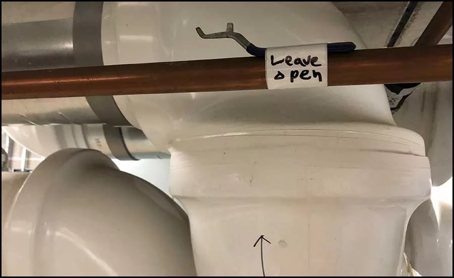
The condenser water return (CWR) piping leading to the top of the cooling tower froze one winter and catastrophically ruptured. The CWR drain valve had opened when the system transitioned out of Chiller Mode as it should, but a manual isolation valve located on the that drain line had been closed by someone who didn’t understand the system. One cannot prevent everything, but you can remove the valve handle and make a pretty sign to minimize the pain (see Figure 4). As an added safety net, we now position the cooling tower bypass valve to 50% in Dry Cooler Mode and Disabled Mode to allow for a separate path (the tower bypass pipe) for water to drain back to the remote sump.
We initially used the previous, fixed values for Condenser Water Supply Temperature Setpoint and Chilled Water Supply Temperature Setpoint. But our strategy for the MAU reduced the load drastically in milder temperatures, since we were not overcooling anymore at the MAU. The combination of low thermal load and high lift placed on the chiller resulted in the chiller tripping out on surge protection. To promote stable operation of the chiller during lower ambient conditions while in Chiller Mode, we needed to implement aggressive condenser water and chilled water supply temperature setpoint resets.
The combination of modulating the glycol chilled water pump while in Dry Cooler Mode, and eventually cycling it on and off at minimum speed, allows for us to operate stably without risk of freezing into much colder ambient conditions.
Supply air temperature control of the MAU was initially very poor during drier summer days with minimal reheat load. Adjustments to the boiler staging and modulation parameters on the boiler plants’ controller, along with implementing an upper limit on the HX-2 control valve position during such scenarios, drastically improved the system’s ability to track MAU supply air temperature on setpoint.
Conclusion
These three articles on utilizing the MAU cooling coil as a dry cooler were intended to inspire some creativity in the solutions you are finding for your clients. Every case study presented had its unique set of challenges, and I would be lying if I said the sequences we landed on came without strife. There were plenty of lessons learned along the way. Very close coordination with the controls contractor in each instance was needed, as these were non-conventional sequences, and proper control of all the equipment at high turndown ratios was needed to make these work effectively. I am proud of where all the projects landed and know I learned a ton along the way.
Looking for a reprint of this article?
From high-res PDFs to custom plaques, order your copy today!