How to Reverse Engineer a Part from a 2D Scan
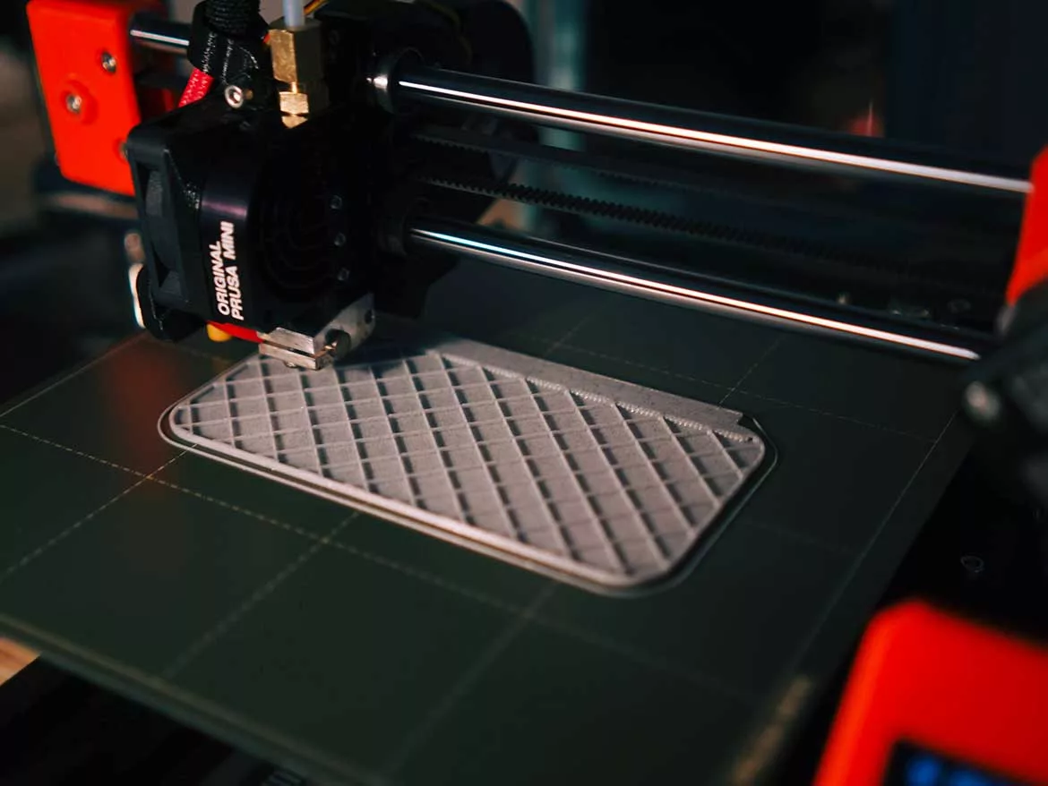
Once your CAD model is complete, you can use it to manufacture a new copy of the part. If you have access to a 3D printer or CNC machine, you can do this yourself. Image courtesy of Kadir Celep
You have a part that you need to recreate, but you don’t have a 3D model — meaning you can’t move straight to machining or printing a new part.
So long as you have the part, however, and some additional equipment like a camera and caliper, you can reverse engineer the part, converting an image or 2D scan of the component into a CNC machine- or 3D-printer ready file.
Below, we’ll break down how to reverse engineer a part in this way, plus potential uses for your new CAD model.
Step 1: Gather Your Materials
Before you begin, you’ll need to have a few materials on hand:
- A part you want to reverse engineer;
- A high-quality scanner or camera;
- Measuring instruments, like a caliper or micrometer;
- A CAD modeling tool, like FreeCAD, AutoCAD, or Autodesk Fusion 360;
- Some way to create your new part, like a CNC machine or 3D printer; and
- Optionally, a photo editing tool that is capable of converting a raster image to a vector.
If you don’t have access to a scanner and plan to use a camera, you should also have a good place to take a picture of your part — ideally, a surface with a solid-color background that contrasts with the part you’re trying to recreate.
A lamp or light can help to make the part more visible in the image you capture, but good lighting isn’t essential, so long as the shape of the object is clear in the image you capture.
Step 2: Capture a 2D Scan (or Image)
Parts that are especially flat can typically be scanned with a normal optical image scanner, the kind you use to scan documents.
Simply lay the part on the scanner and scan them as you would a document. You may need to take care to avoid scratching the surface of the scanner if the part has sharp edges.
Either send the scan directly to your computer or to a location you can easily access from your computer and then download it.
If you don’t have easy access to a scanner, you can also use a camera. Place the part on a solid-colored surface that contrasts with the color of the part. White or black will typically work best.
Try to hold the camera as level with the surface as possible. The less level the camera is, the more distortion there will be in the final photo. You’ll have to account for this distortion when converting your photo into a CAD model.
A camera also works well for capturing an image of a part that isn’t perfectly flat, like a knife’s handle, but doesn’t have too much depth or vertical complexity.
Once you have a photo that clearly captures the part, send it to your computer.
Step 3: (Optional) Convert Raster to Vector
Now that you have a reference photo for your part, you can begin creating a model. You have two options for how to start — you can either trace over the photo in a vector image editing program, like Adobe Illustrator or Inkscape, or begin directly in your CAD program of choice.
This step isn’t completely necessary, but it can make the CAD modeling process a bit simpler. Many CAD modeling programs will convert the SVG object into an extrudable profile or profiles automatically when imported.
If the profile looks good, you can calibrate the profile, extrude the profiles to the desired thickness, and make any necessary changes — like added filets. Then, you’ll be ready to print or machine your part.
If you’re familiar with the UI of your CAD tool of choice, however, it may actually be more straightforward to skip to the next step.
If you’ve never worked in a CAD tool before, the relative user-friendliness of the vector image editing program may help you develop a clear outline of your part that will translate well to a CAD model.
To do so, start by importing the scanned image of your part into your vector image program. Use the program’s drawing tools to trace a vector image over the raster image of your scanned part.
Once you’re finished, export the completed file into a neutral, non-proprietary file format like SVG, PDF, or EPS. This will ensure that you can open your file in your CAD software of choice.
Step 4: Sketch Your CAD Model
First, import your image into your CAD software. Adjust the scale of the image and move it until it fits on your screen and is centered.
Create a new layer that you can use to trace over your scanned image. Using drawing elements like the line, arc, continuous curve, or rectangle tools, trace over each element of your scanned part.
Next, you’ll want to calibrate your sketch. The exact process varies from tool to tool but typically involves selecting two points and keying in the value for the distance between those points.
Using the measured distance from your real-world object, you can ensure the reverse-engineered part will be the correct size when printed or machined.
Now, you can clean up your sketch and prepare your model for export. Using your CAD software, extrude the part until the model is the correct thickness. If the part has rounded edges, you can use a fillet or chamfer tool to shape edges as necessary until the model correctly represents the part.
You’re now ready to save the model and export it in a neutral file format that can be used for printing or machining your part.
What Parts Can I Use This Method For?
This method is a good way to reverse engineer many different types of parts. The flatter the part, the more effective this method will be.
Gaskets, mounting plates, handles — so long as the part is mostly flat, this method can be a simple way to reverse engineer it.
It is possible to recreate more complex objects using this method. However, the more three-dimensional the part is, the more likely it will be that you’ll need a different approach. You may need to take multiple images of the part, one from each angle, and carefully reconstruct the part’s three-dimensional structure in your CAD software.
In general, reverse engineering works best with simple objects. If you need to recreate a part that is particularly complex, you may want to begin with reaching out to the manufacturer for model files or searching online to see if someone has already recreated the part themselves.
What Can I Do With My CAD Model?
Once your CAD model is complete, you can use it to manufacture a new copy of the part. If you have access to a 3D printer or CNC machine, you can do this yourself.
With a 3D printer, it’s typically easiest to create plastic parts — though some new companies are making it easier to print metal objects with new 3D printing technology. A CNC machine will also be effective for making metal parts.
If you can’t manufacture the part yourself, you’ll need to get in touch with a manufacturer who has the tools needed to create the part. After sending them the CAD file, they will provide you with an estimate of how much the part will cost to manufacture, as well as an estimate of how much time they will need.
You can also host the CAD model online, allowing anyone else with access to a 3D printer or CNC machine to use the model to make the part on their own.
Looking for a reprint of this article?
From high-res PDFs to custom plaques, order your copy today!


