The Proper Design Criteria for Selecting the Appropriate Pump

A properly designed pump network is critical to the success of any hydronic mechanical system. Using rules of thumb and general principles is a good starting point when designing the layout of a pumping system; however, it is important the engineer has a thorough understanding of pump design fundamentals in order to make better informed decisions throughout the design process.
At minimum and prior to selecting a pump, an engineer should identify the following design criteria, as applicable to the project: 1) closed versus open system; 2) the pumping approach (i.e., constant or variable flow); and 3) series versus parallel pumping arrangement.
A closed-loop system has no piping open to the atmosphere. Examples of closed-loop systems are chilled water and heating hot water systems. An open-loop system has piping exposed to the atmosphere.
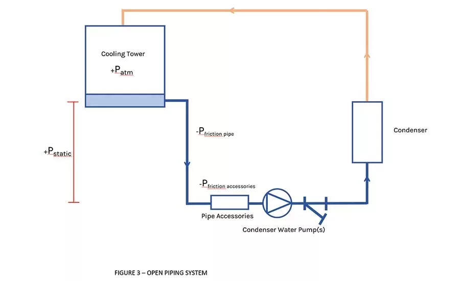
A cooling tower piping system’s spray nozzles (discharge side of the pump) at the top of the tower are open to the atmosphere, and the basing of the tower (suction side of the pump) is also open to the atmosphere, making this an open-loop system.
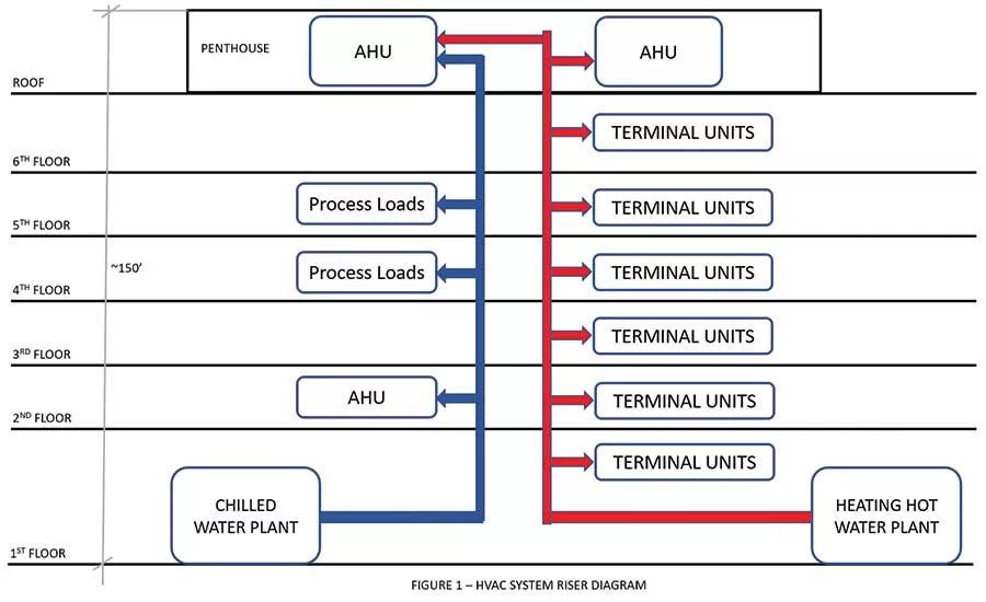
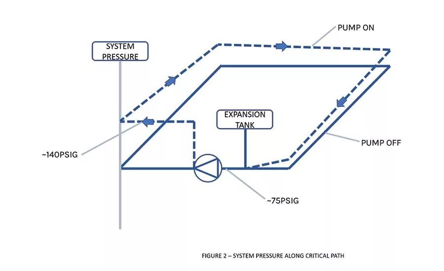
In a closed system, several factors are included when calculating the head of the pump are: 1) pressure drop (in feet of water) through the piping system; 2) pressure drop through a fitting; 3) pressure drop through valves, including control valves; and 4) pressure drop through the HVAC equipment (i.e., chillers, boilers etc.). Static head is not included in the pump head calculations for a closed-loop system; however, the static head plays an important role in determining the design of the pump (i.e., working pressure) and the associated mechanical equipment it serves. In the example shown in Figure 1, the pumps are located at the base of the building, approximately 150 feet below the highest point in the system; assuming a 10-psig pressure at the top of the system, the fill pressure of the system will need to be approximately 75 psig (65 psig to overcome the height difference plus 10 psig). This pressure (75 psig) represents the static head of the system — it’s the pressure the pump “sees” before it is energized. Assuming the dynamic head (i.e., the pressure drop through the entire piping system, including the fittings and accessories) is approximately 65 psig, the discharge pressure at the outlet of the pump will be approximately 140 psig.
Figure 2 shows a diagrammatic representation of the system piping pressure along the critical piping path. It is important to note that when the pump is off, the pressure within the piping system is not constant across all floors; the lower floors will experience higher static pressure than the upper floors.
No two hydronic systems will be the same, and the location of the pumps within a loop will differ based on the type of hydronic system being designed. Typically, in heating hot water systems, the pumps are located downstream of the boilers (pull-through configuration); this is because standard hydronic condensing boilers are typically constructed for a maximum operating pressure of 150 psig. As shown in the aforementioned example, the 140-psig discharge pressure will be close to the maximum allowable working pressure of the boilers. To mitigate the risk of operating at or close to the maximum allowable working pressure of the boiler, the pumps are placed downstream of the boilers such that the boilers “see” a much smaller pressure, typically slightly above the static pressure of the system. Further, boilers and heat exchangers, unlike chillers, have a low pressure drop, low operating pressure, and are affected by a sudden change in differential pressure when a pump turns on and off. If the pump is placed downstream of the boiler or heat exchanger, the pressure is greatly reduced in the system at the point of the boiler, so no increase in operating pressure is required for boiler selection. Additionally, if the pump was placed discharging into a boiler or heat exchanger, the influx of differential pressure when the pumps turn on and off is seen by the associated pressure relief valve. This may cause the pressure relief valve to dribble or open every time a pump turns on.
In regard to chilled water systems, a good design practice is to have the pumps located upstream of the chillers (push-through configuration); the pump will have to provide enough head to pump through the evaporator section of the chiller, piping losses, and any additional coils and valves along the way. Chillers have large pressure drops and are generally rated at 150- or 300-psig operating pressure. By placing the pumps upstream of the chiller, the operating pressure for the rest of the HVAC piping system could be reduced to 125 psig or less since the pump head is first being decreased significantly by the chiller pressure drop before entering the piping system. This approach could save significant material costs during the construction of the HVAC piping network. Another aspect to consider is that pumps and associated accessories are difficult to insulate perfectly. By placing pumps upstream of the chillers, the return chilled water creates higher surface temperatures than the supply chilled water would, which mitigates condensation risk on the imperfectly insulated pumps and accessories.
In condenser water loops, net positive suction head (NPSH) tends to play an important role in pump placement due to the system being open to the atmosphere. NPSH refers to the amount of pressure a pump needs to avoid cavitation, which is caused by fluid vaporization from lack of pressure. Manufacturers list the NPSH required (NPSHr) for every pump, which equates to the pressure required to keep the pump from cavitating. NPSHr is critical because pumps operate at a lower pressure at the impeller and inlet to the impeller vanes than the pressure available at the suction inlet of the pump. This means that even if the pressure measured at the inlet to the pump is above the point of liquid vaporization, cavitation can still occur after the pressure drop from the inlet to the interior of the pump. By listing the NPSHr, designers can determine the NPSH available (NPSHa) and ensure it is above the NPSHr to reduce risks of pump cavitation. The NPSHa calculation considers all piping/equipment loss from the cooling tower basin (atmospheric pressure) to the suction inlet of the pump, and is described as:
NPSHa = Patmosphere + Pstatic - Pfriction – Pvapor pressure
It is best practice to avoid putting any accessories or pieces of equipment with a high pressure drop, like strainers, on the discharge side of the pump, as seen in Figure 3. This mitigates the risk of increasing the friction loss and reducing the NPSHa below the NPSHr.
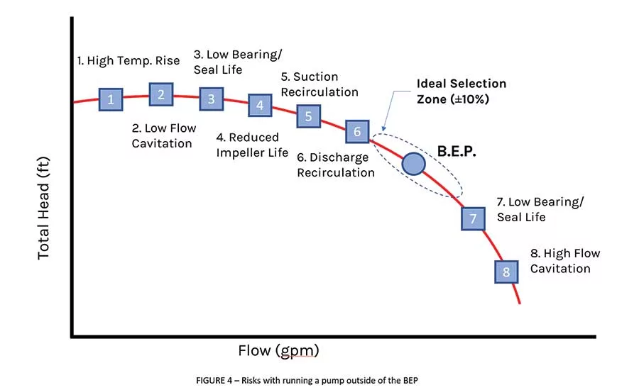
Regardless of the mode of operation (i.e., constant flow or variable flow), a pump should always be selected at or close to the best efficiency point (BEP), which is defined “as the flow at which the pump operates at the highest efficiency for a given impeller diameter and represented as a point on a pump curve plotting rate of flow and head, for a significant period is ideal but often not carried out.”
The risks of operating a pump continuously or for long durations at rates of flow greater than or less than the pump’s BEP rate of flow are discussed in ANSI/HI 9.6.3-2017, “Rotodynamic (Centrifugal and Vertical) Pumps — Guideline for Allowable Operating Region.”
As shown in Figure 4, operating a pump at a flow greater or less than the BEP may create unmitigated risks, including the risk of cavitation, vibration, impeller damage, and reduced bearing and seal life. These risks could be mitigated by keeping the flow rate in the preferred operating region (POR). As defined by ANSI/HI 9.6.3-2017, the POR is “a range of rates of flow to either side of predicted BEP within which the hydraulic efficiency and the operational reliability of the pump are not substantially degraded.”
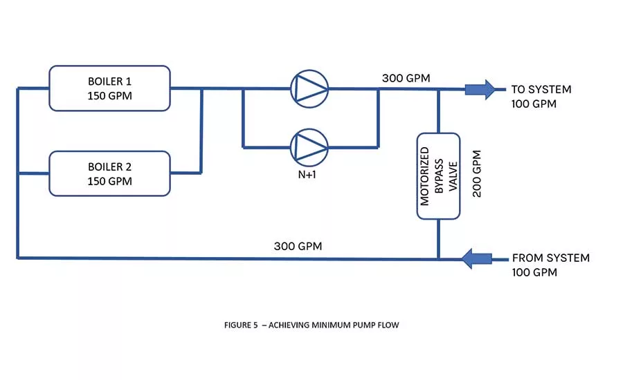
Selecting constant flow pumps at or close to the BEP is relatively straightforward. The same could be considered when selecting variable flow pumps; however, the engineer should also consider the minimum flow requirements for the pump, in particular when selecting pumps that serve variable primary-only heating hot water systems. It is not uncommon for condensing boiler manufacturers to state that their boilers have no minimum flow requirements. As discussed by authors in previous articles, this statement could lead the engineer to assume that the water flow through a boiler could be as small as possible without affecting the operation of the boiler; after all, the lower the flow, the less pumping energy will be consumed. In the case of variable primary flow, heating hot water systems at minimum water flow through the boilers should be either the sum total of the minimum flow requirements through each operating pump or the sum total of the minimum flow requirements associated with the minimum firing rate of each boiler, whichever is larger. As shown in the example in Figure 5, the minimum system water flow associated with the minimum firing rate of each boiler may be 100 gpm for a total system flow of 200 gpm. However, if the minimum flow required by one operating pump is 300 gpm, the system motorized bypass valve will need to modulate open to maintain 300 gpm and not 200 gpm. Assuming both boilers are firing, each boiler will receive 150 gpm.
In a primary-secondary chilled water system, and as shown in Figure 5, the primary pump placement follows the same logic as the variable flow chilled water system previously discussed. However, in this type of system, the primary pumps serve as constant flow through the chillers, while the secondary pumps are in a separate loop serving the building loads. These two loops are connected by a common pipe, which allows the flow from the chillers to vary through the secondary loop to the building loads. The crossover bridge refers to the segment of piping from the primary loop that connects the primary supply and the return to the common pipe. The secondary pumps should be placed to discharge into the secondary loop and not into the common pipe. This allows the secondary pumps to have an increased circuit pressure over the primary loop system pressure, which flows through the crossover bridge. Also, the common pipe can be considered as a compression tank, which equates to a no-pressure change point. Therefore, if you place secondary pumps discharging into the common pipe, there will be an immediate loss in the secondary loop static pressure.
Regardless of the system approach, i.e., primary, secondary, or variable primary only, it is a common design practice to design pumps to operate in parallel. As such, understanding the system curve with two pumps running in parallel is of extreme importance in order to have a well-operating pumping system. It is important the system curve intersects the curve of both pumps, so that in the scenario of one pump failing, the remaining pump will be able to support the flow of the system. If the system curve does not intersect both pump curves when one pump fails, the remaining pump will be operating near or at the high flow cavitation point, as seen in figure 4.
Looking for a reprint of this article?
From high-res PDFs to custom plaques, order your copy today!