VRF Technology — The Missing Link to Lower Utility Bills
VRF offers highly efficient performance, long life cycles, quiet operation, less downtime, and more.
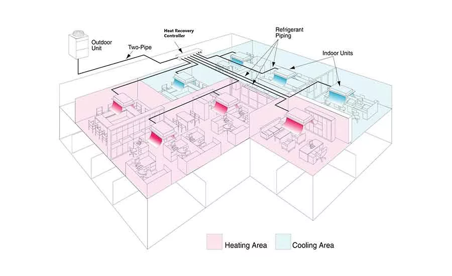
FIGURE 1. VRF system control demand with different zone needs.
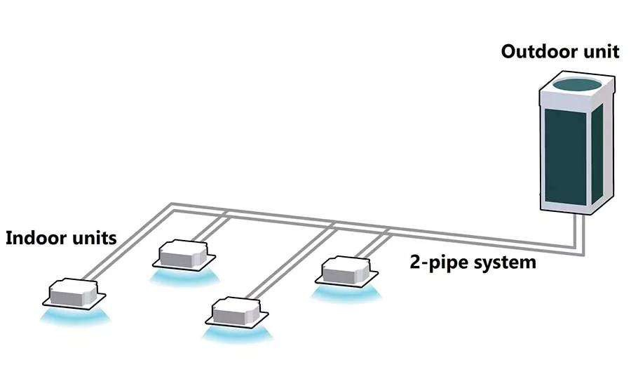
FIGURE 2. VRF heat pumps system.
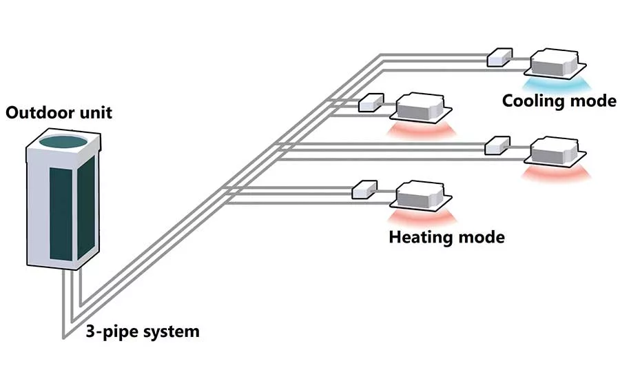
FIGURE 3. VRF heat recovery system.
Variable refrigerant flow (VRF) systems are popular options in both residential and customer facilities. These systems are essentially improved versions of multi-split systems and use refrigerant to heat and cool buildings. They can operate as heat pumps (heat or cool only) or with simultaneous heating and cooling based on various needs throughout the building. This allows for precise zoning for maximum thermal comfort. VRF systems consume very little energy as demonstrated on energy bills. VRF systems can easily be added into existing or future BAS. Additionally, VRF HVAC technology minimizes the necessary ductwork and excludes the need for chilled/hot water distribution and any associated costs.
VRF consists of a single outdoor unit, single or multiple indoor units serving different zones, and refrigerant piping with branch selectors and associated controls. The outdoor unit consists of the compressor, which compresses the refrigerant, and an indoor unit that acts as an evaporator. Each outdoor unit may be connected to multiple indoor fan coil units. The outdoor unit can have one or multiple compressors. These compressors are typically inverter-driven scroll or reciprocating units, which means they use a drive to control the compressor’s motor speed and modulate the cooling capacity. These compressors are usually scroll or reciprocating. The speed is varied based on the power supply frequency to the compressor. As the compressor speed changes, so does the refrigerant flow delivered by the compressor to the indoor units.
There are metering devices installed on each fan coil unit, which are controlled by the indoor units themselves or the outdoor unit. Each fan coil unit communicates with the outdoor unit the level of refrigerant flow necessary to meet the individual requirements of the indoor units. Considering the aforementioned capabilities of VRF systems, they are suitable for applications with part-load requirements based on past usage as well as applications that require zoning and individual temperature control.
Usually, R-410A is used as the heat transfer refrigerant in VRF systems. Using this refrigerant makes VRF systems exceptionally efficient and allows them to boast EERs as high as 20 and IEERs of 17-25. VRF systems are typically 20-30% more efficient than conventional HVAC systems. This high level of efficiency is achieved due to partial load operation, speed modulation, zoning capabilities, and heat-recovery technology. The safety classification of R-410A in ASHRAE Standard 34 is group A1: nontoxic and nonflammable refrigerant with zero ozone-depletion potential.
VRF system types
Cooling-only systems (less popular): This system is very similar to an air conditioner. It can only cool; heating is not an option.
Heat pump systems (most popular): This system can either cool or heat at the same time. VRF heat pumps are used in restaurants, lobby areas, clubhouses, or religious facilities where there is a defined cooling or heating mode of operation for the entire building. VRF heat pumps are two-pipe systems.
Heat recovery systems (average popular): Heat recovery units are the most sophisticated VRF configuration. Cooling and heating are available via each indoor unit independently at the same time. One unit might be in cooling mode while the one next to it is operating in heating mode. VRF heat recovery is used in schools, office buildings, historical buildings, hotels, assisted living facilities, banks, and other commercial buildings where simultaneous cooling and heating is a design requirement. VRF heat recovery units operate in three-pipe configurations.
Design Flexibility
One of the major benefits of VRF technology is its design flexibility, as it can be utilized with a number of products. Multiple kinds and sizes of indoor units are available to satisfy different application requirements. Designers should always take into consideration the piping capabilities of different systems. Two important, key elements to review regarding the piping capabilities of any VRF systems are:
I. The maximum elevation difference allowed between the highest and lowest indoor units; and
II. The distance allowed from the outdoor unit to the farthest fan coil on the system.
Installation
VRF installations are known to be very cost-effective and easy when compared to traditional HVAC systems, which usually require ductwork or large pipe sizes, pumps, boilers, etc. VRF outdoor units are light in weight, small, and barely have any footprint. This small sizing eliminates the cost of renting a crane to lift the unit for rooftop installations. In most cases, the outside unit can be installed on the ground if there is enough space. Also, since they are very lightweight, no additional support or beam is required to support the weight.
Since these systems are very similar to residential air conditioning systems, some contractors may perform the insulation without any guidance from the insulation contractor or the manufacturer. In the past, it was observed that there were several areas in a VRF system that were left under-insulated. The following areas are commonly left uninsulated by contractors:
a) Valves, fittings, and pipe support;
b) Insulation termination points;
c) Seams of butt-ends and longitudinal seams of insulation materials;
d) Electrical “zip-ties” used as anchoring and closure devices; and
e) Rooftop piping.
Comparison of VRF systems
The type of compressor used in the outdoor units is the primary distinguisher between VRF systems. Based on compressor types, VRFs are categorized as the following:
- Single variable-speed compressor;
- Variable-speed compressor plus fixed-speed compressor; and
- Multiple variable-speed compressors.
Single variable-speed compressor: This type of system has only one compressor. Usually it’s a scroll compressor and has a large capacity. The compressor starts and runs the system when there is a demand in the building. Since there is only one compressor, there is no backup compressor in case the compressor fails.
Variable-speed compressor plus fixed-speed compressor: There are two compressors in this type of system. One inverter-driven compressor starts and runs the system all the time. It ramps up until the demand is above the compressor’s capacity, at which time the constant-speed compressor starts and works at 100%. As the result, the inverter-driven compressor slows down. Since this system has two compressors, it provides backup in case one of them fails.
Multiple variable-speed compressors: These types of systems have multiple inverter-driven, twin rotary scroll compressors. Multiple variable-speed compressors have many advantageous over the previous types, as they provide more reliable backup capability. If one of the compressors fails, the system will adjust and balance out the load between the other two compressors, and there won’t be any change in the comfort condition in the space until the broken compressors are replaced. The starting sequence is rotated between all the compressors, equalizing the operating time, thus minimizing unnecessary excess operation of any of the compressors. Multiple compressors with variable-speed capabilities offer a better part-load performance — IEER can be as high as 25. Also, when the load is minimum, the system can adjust the load so only a minimum number of compressors at the minimum speed are required to meet the demand.
Summary:
VRF technology was first implemented in the U.S. in 2002. Since then it has become very popular between building owners and contractors. VRF systems route two- and/or three-pipe refrigerant from one outdoor unit throughout multiple indoor units in each zone. One of the most important features of VRF is its capability to provide heating and cooling at the same time in different zones. Besides that, VRF systems offer the following advantages:
Higher energy efficiency: VRF systems may be equipped with inverter-driven compressors. Having the inverter lowers the energy bills by 25% or more.
Lower life cycle costs: VRF installation and maintenance costs are much lower than conventional HVAC systems.
Delivering fresh air: With high-quality, advanced filters, individual room temperature control, full integration with ventilation systems, etc., VRFs can provide optimal comfort levels in a space.
Limiting operational noise: VRF systems keep operational noise levels lower than whisper-quiet levels. Whispers come in at 35 decibels; VRF indoor units operate as quietly as 27 decibels. Outdoor units are also quieter than traditional systems.
Varying loads: VRF units are designed to modulate the refrigerant flow to meet the space requirements. Inverter compressors deliver only the amount of cooling/heating needed to match each zone’s demands. VRF technology uses integrated controls and temperature sensors to measures the comfort condition at each zone, hence the compressor adjusts its speed to provide desired conditions.
Solving comfort issues: VRF zoning offers personalized comfort control in each individual room. It’s also capable of simultaneously heating and cooling different zones.
Less downtime: VRF HVAC systems are intended to run only when cooling/heating is needed and under partial-load conditions. This means there is less wear and tear on the equipment parts, and the system will have fewer breakdowns.
Requires less space: One of the main benefits of VRF HVAC systems is that they don’t require any ductwork to deliver zoned comfort. No ductwork means no unnecessary space in walls and ceilings for the equipment.
Looking for a reprint of this article?
From high-res PDFs to custom plaques, order your copy today!


