Danfoss Online
The Synchronized Hydronic Loop
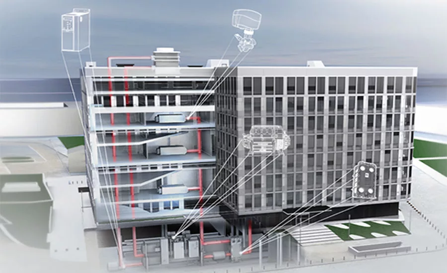
A building’s hydronic HVAC system is rarely just the sum of its parts. The system is comprised of chillers, boilers, pumps, VFDs, AHUs, and valves that create a loop through which water is circulated to control the building’s temperature and its occupants’ comfort. In this loop, each component is a node that has an effect not just on the one next to it but on every other one, regardless of how far they are from each other. In fact, the nodes furthest from each other may impact each other the most. Variable speed pumps, for example, surrender much of their part-load efficiency if the wrong balancing valves are installed at the terminal units. Too often, systems are designed and components specified as though this loop is made of discrete nodes. Consequently, building owners continue to install inefficient systems and then struggle to find lasting solutions to chronic problems like hot spots, high utility bills, and constant maintenance calls.
A system composed of synergistic components, on the other hand, enhances the efficiency of the entire loop. Pressure independent control valves (PICVs) installed at the AHUs tightly control the water temperature entering and exiting the unit’s coils, allowing the chiller’s oil-free variable speed compressor to work as efficiently as possible. VFDs on the pumps supply only as much water as is demanded to take advantage of part-load conditions to save energy. All the while, each component collects valuable data on energy usage, flow, pressure, and temperature for the BMS to aggregate and use to make decisions about predictive maintenance, fault detection, and comfort.

Investing in a synchronized hydronic loop made of synergistic components ultimately offers solutions to three common problems associated with conventional hydronic HVAC systems:
- Occupant comfort;
- Design efficiency vs. installed efficiency; and
- Degradation of efficiency over time.
These problems are often symptoms of an unbalanced system but are frequently misdiagnosed as issues with individual components. Those disconnected components, however, are operating as best they can in a system not at equilibrium.
Precise Comfort Control
A traditional HVAC system is designed using manual balancing valves to provide proper flow to all coils during the hottest and coldest days of the year, which typically occur just 2 percent of the time. These balancing valves, however, possess a fixed orifice that remains in the same open position the other 98 percent of the time, allowing the system’s differential pressure to change and thus flow to the coils to shift even as loads remain constant. Ideally, flow should vary only in response to changes in load.
This improper flow at constant load creates a situation known as “hunting,” which causes inefficient heat transfer, spikes in chiller and pump energy consumption, dramatic swings in discharge temperatures and, ultimately, chronic hot and cold spots in the occupied space.

The PICVs in a synchronized hydronic loop, on the other hand, continuously adjust their differential pressure orifice position in response to dynamic load conditions, maintaining consistent differential pressure across the valve. This means the flow into the coils only varies in response to changing loads, allowing for efficient heat transfer and precise comfort control in the occupied space.
Design Efficiency in All Load Conditions
It’s easy to assume that achieving maximum efficiency in an HVAC system means sacrificing comfort. After all, conserving energy at home usually means turning up the thermostat beyond the point of comfort. When it comes to hydronic HVAC systems, however, comfort and efficiency are two sides of the same coin.

As the PICVs at the air handlers continuously adjust to current load conditions to optimize heat transfer and comfort, they’re also minimizing flow into the coils. This means the system is only heating, cooling, and pumping as much water as is necessary to meet demand. A synchronized hydronic loop utilizes variable speed pumps and oil-free, variable speed compressors to match the system’s energy consumption to that demand, allowing the system to achieve design efficiency in all load conditions.
Sustained Efficiency Over Time
Regardless of where a system starts out, its efficiency will decline with time. Chillers with traditional compressors degrade at a faster rate as oil from the chiller mixes with the refrigerant and contaminates the system. That could lead to an immediate efficiency decrease of 7 percent, eventually climbing to a peak of around 20-30 percent efficiency loss; however, a synchronized hydronic loop utilizes oil-free chillers, completely avoiding these issues. Instead of oil, these chillers use magnetic rotors to eliminate friction. This technology not only allows the system to maintain a high level of efficiency but also significantly reduces maintenance costs.

The synchronized hydronic loop offers solutions to many of the problems associated with conventional hydronic systems. It also proves that a systems-based approach, as opposed to selecting components individually, is necessary to maximize efficiency, decrease downtime, and, ultimately, improve occupant comfort and the bottom line. The efficiency of each component in the synchronized hydronic loop is superior to the efficiency of that same component in a system without the other components. In this way, the synchronized hydronic loop is truly greater than the sum of its parts.
Looking for a reprint of this article?
From high-res PDFs to custom plaques, order your copy today!


