Temporary Cooling Tower: Short Term, Big Impact
A temporary cooling tower facilitates permanent chiller plant upgrades at Walter Reed.
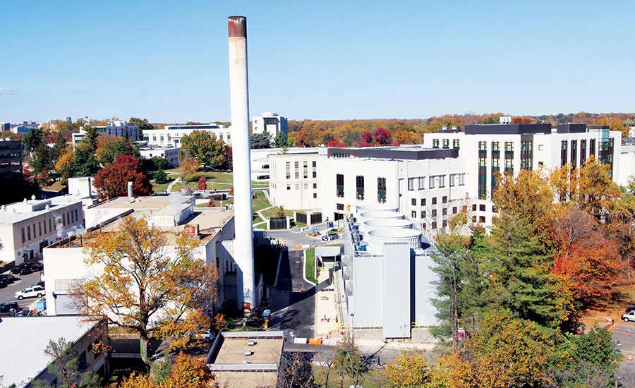
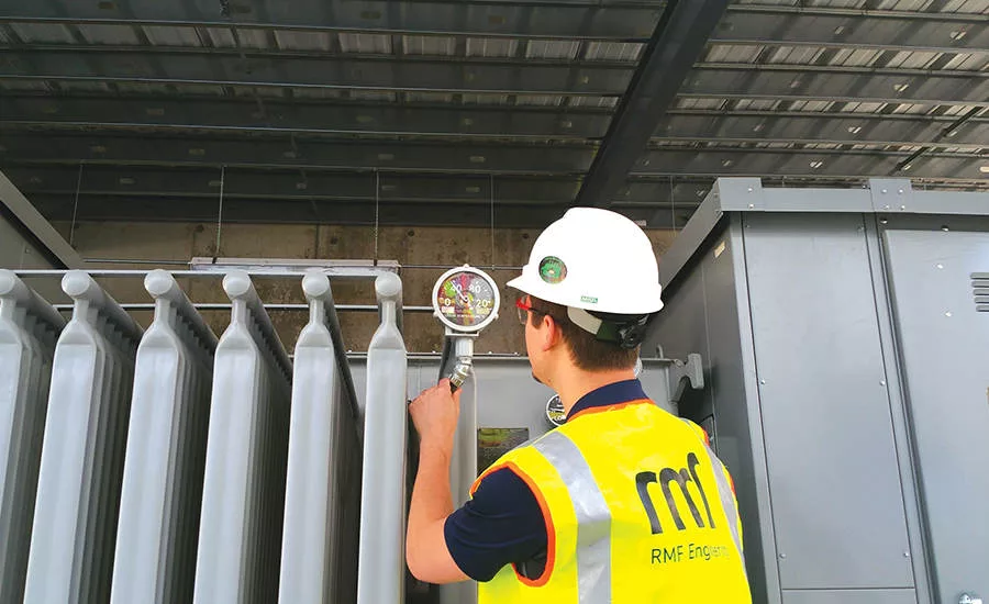
FIGURE 1. A temporary substation transformer was installed to support the temporary cooling towers. (Photo courtesy of RMF Engineering)
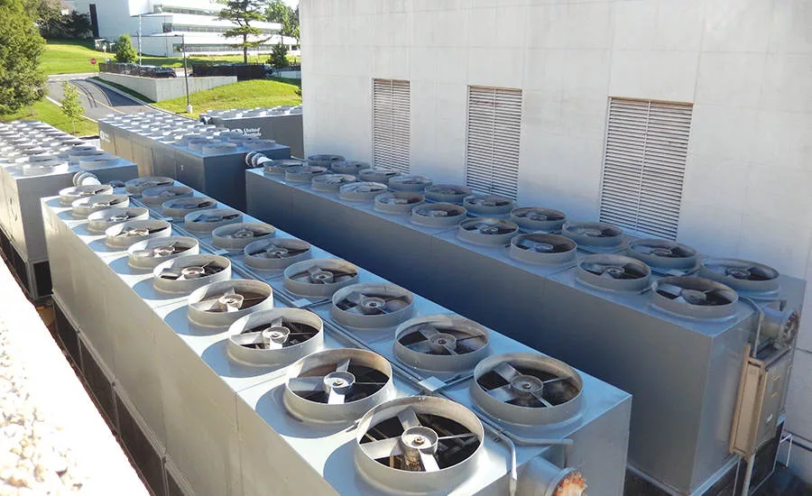
FIGURE 2. Once assembled, the temporary cooling tower when assembled provided nearly 15,000 tons of heat rejection for the chiller plant. (Photo courtesy of RMF Engineering)

FIGURE 3. Permanent cooling towers went online in the fall of 2016 at the Walter Reed National Military Medical Center, successfully accomplishing the project in the planned timeframe. (Photo courtesy RMF Engineering)
Due to the Base Realignment and Closure (BRAC) program, Department of Defense facilities across the country were consolidated to improve efficiency and reduce operating costs. One of the reorganizations involved the relocation of the Walter Reed Army Hospital in Washington to the National Naval Medical Center in Bethesda, MD. The reorganized facility contains over 2 million sq ft of medical, research, and support space. This combined campus, known as the Walter Reed National Military Medical Center (WRNMMC), provides medical treatment for active and retired personnel and their families from every branch of the military.
By consolidating the two medical campuses, the intensity of air conditioning loads on the original campus central cooling system increased significantly. At the heart of the campus chilled water cooling system was a 13,500-ton chiller plant that relied on a 3-cell, 40-year-old induced draft crossflow cooling tower. The cooling tower was aging, nearing full capacity, and consuming energy and water inefficiently. Replacing the cooling tower would require de-energizing for several months, which was iblematic since year-round cooling loads needed to be satisfied.
To tackle this challenge, the Naval Facilities Engineering Command (NAVFAC) in Washington committed $28 million in funding to utilizing the design-build delivery method for the engineering and construction of the cooling tower. The project would require the design-build team to provide close supervision and coordination in order to achieve the phasing of work necessary to maintain campus cooling. NAVFAC was assisted by Jacobs Engineering Group Inc. in the development of schematic designs, requests for proposals, and commissioning. The design-build contract was awarded to The Walsh Group, and the design-build team led by Walsh included mechanical subcontractor Green Contracting Company Inc. and designer RMF Engineering Inc.
Project Scope
The existing induced-draft crossflow cooling tower was constructed largely of wood with corrugated asbestos panels. The cooling tower consisted of three individual cells with a common cold water basin and manifold piping for equalization and the collection and distribution of condenser water. This cooling tower provided heat rejection for as many as nine chillers with approximately 1,500 tons of refrigeration capacity each. Because the cooling tower was constructed of wood, it was equipped with a deluge fire protection system and fire pump. The cooling tower was fixed above a large welded steel cold-water basin that was supported on steel framing. The basin consisted of three compartments, one for each cell. Below the basin was a multi-level concrete structure that housed piping, pumps, and other systems associated with the cooling tower.
In addition to replacement of the original three cooling tower cells, the project required that a fourth cell be added to support future cooling loads and system reliability. Age and wear had resulted in damage to the cooling tower fill, louvers, and structural components, and it had reached the end of its useful life. Historical operating data determined the required amount of cooling each month for the purpose of determining whether all or part of the cooling tower could be taken offline for replacement. RMF Engineering investigated options for partial demolition and replacement while portions remained were considered operational, but this presented an operational risk. Properly replacing the cooling tower would require de-energizing, draining, disassembling, and reconstructing the tower, resulting in several months without cooling for the campus.
Since it was not feasible to suspend cooling for the duration of construction, alternate means of heat rejection would be required. Construction of a temporary cooling tower on a property adjacent to the plant, with proper phasing, would allow the cooling plant to continue operation during construction of the new cooling tower and concrete structure below. Based on the anticipated construction schedule, the capacity of a temporary cooling tower would need to be chosen to reliably support the full campus peak summer cooling load.
The team evaluated temporary cooling tower configurations and conducted an exhaustive search for large-capacity rental cooling tower equipment. Understandably, no single device was available that could be reasonably shipped and erected at the site to provide the required heat rejection capacity, so the team pursued a modular approach using large individual units. United Rentals proposed the delivery and assembly of portable induced-draft counterflow cooling towers mounted on mobile trailers. The flow needed to replace the capacity of the cooling tower and keep N+1 redundancy required a peak condenser water flow rate of 36,000 gpm. This meant that it would be necessary to have as many as five tractor trailers housing nearly 3,000 tons of heat rejection capacity each, with the capability of 9,000 gpm flow. When assembled, the modular system would provide nearly 15,000 tons of heat rejection for the chiller plant.
Phases 1 & 2: Early Tie-ins and Temporary Cooling Tower
To minimize disruption to the chiller plant and cooling for WRNMMC, key tie-ins were made in the chiller plant condenser water piping system during the winter so that the temporary cooling towers could be connected and disconnected without shutdown of the system later when cooling demand might be greater. The tie-ins required installing two pre-fabricated 30-in piping sections and installing isolation valves.
The temporary modular cooling tower consisted of five units each mounted on a mobile trailer. The trailers were located on approximately 5,000 sq ft of paved service area adjacent to the cooling plant requiring vehicle traffic to be closed and redirected in these areas. Care was required to locate each modular cooling tower so that the sound and discharge plume would not impact surrounding buildings or staff. Certain building openings, doors, louvers, and windows were temporarily sealed.
Each induced-draft counterflow unit utilized 20 direct drive fans that required 480-volt electric service. A temporary 9,000-gpm cooling tower condenser water pump was installed adjacent to each cooling tower and connected to new welded steel 24-in and 30-in pipe headers interfacing the pumps with the cooling tower water outlet and inlet branch pipes. The modular unit water basins were equalized with piping, and the header piping arrangement provided increased reliability. The pumps circulated water to the chiller condensers through 14-in pipes connected to 30-in mains and back to the cooling towers to reject heat. The temporary cooling towers were designed with automatic water temperature controls to optimize fan operation. Basin level controls and overflow drains were included, as well.
Existing chemical treatment systems were modified to maintain water quality, and basin heating and piping heat trace provisions were installed for winter operation. The temporary cooling towers were equipped with custom control panels for water temperature fan control and pump interlocks while providing interface with the plant control system to allow operators the ability to monitor operation and make adjustments at the panels. Since the temporary modular units functioned together as a larger single cooling tower, the chiller plant did not lose efficiency or capacity during the construction of the new permanent cooling tower.
Green Contracting, the mechanical subcontractor, had prior experiences with creating large assemblies of temporary equipment so that utility plants could be renovated, and they knew the key factors in making them successful. For example, selecting the proper equipment, the configuration of the available parking lot areas, along with the ability to access the piping locations contributed to the final selection of the equipment utilized. Once the start-up and commissioning team understood the operations of the plant, personnel trained the existing plant operators in the proper operation of the temporary system.
Making final connections required planning in advance. The team took advantage of a single brief cold weather holiday shutdown to install pipe main tees and isolation valves so that the temporary piping could be later connected and energized without any future interruption.
Temporary horizontal split-case pumps were rented and placed outdoors on grade. Five of these 9,000-gpm pumps were selected and matched with each trailer bank of cooling towers for ease of operation. The pumps were configured with strainers on the discharge side of the pump due to concerns regarding the available Net Positive Suction Head (NPSH). Pumps and tower fans were all placed under manual start and stop control as needed to match chiller load.
The 100 tower fans and five pumps, at 300 hp each, required 480-volt electrical power to operate. This meant that a temporary outdoor substation would have to be constructed with transformation from 13.8 kilovolts (kV) to 480-volt distribution to the temporary equipment. This was accomplished by setting an outdoor, 2.5-megavolt ampere-rated (MVA) transformer with a fan cooled rating of 3.125 MVA to feed a 4,000-ampere, 480-volt temporary outdoor switchboard. The switchboard served the temporary cooling tower and pump motors as well as the construction lighting and miscellaneous control power. To address the concern for reliability, a 1,250-kilowatt (kW) temporary generator was also connected to the switchboard to power a portion of the cooling tower farm in the event of a utility outage. Mike Miller of United Rentals has been assembling and dispatching large portable cooling systems for 13 years. He explained, “We see lots of 300-, 500-, and 1,000-ton applications but a 15,000-ton system is just not as common.”
Phase 3: Permanent Cooling Tower Replacement
The design-build team designed the temporary cooling tower system so that it could be utilized for a year while the permanent cooling tower was demolished and replaced. Once the temporary cooling tower was operational, the original cooling tower system was taken apart in pieces while hazardous material abatement procedures were followed. Within two months, the existing towers were demolished and the original steel basin was exposed and removed. The original basin support steel framing was then accessible and could be inspected, cleaned, repaired, and painted.
A new .25-in-thick 304 stainless steel basin was constructed on top of the steel framing. The basin was constructed of plates with welded seams using an automated submerged arc welding method making it watertight. Basin partition walls were installed to allow separation of cells. Below the basin was a two-level concrete structure with a piping level and pump gallery where multiple split case pumps were located. Two new permanent 400-hp pumps were added to bring the total installed pumping capacity to 45,000 gpm. VSDs were installed on all existing and new 480-volt pumps to optimize pumping energy.
The new counterflow cooling tower selected has four cells in place of the original three and provides up to 17,668 tons of heat rejection capacity, which is 33.3% more than the original. The cooling tower reduces condenser water temperature from 95ºF to 85ºF at an ambient design wet-bulb temperature of 78ºF. The cooling tower was constructed utilizing a fiber reinforced plastic (FRP) internal structure with FRP casing, end walls, wind walls, partition walls, air intake louvers, fan deck, and fan stack. Each individual cooling tower cell is equipped with a 200-hp, right angle gear drive fan to drive a 28-ft-diameter, 13-blade fan. All fans when operable at full speed move nearly two million actual cubic feet per minute (ACFM) of moist air. Energy and environmental benefits include VSDs for fan motors. The cooling tower uses less make up water because of its control of “drift.”
Crews worked from May 2016 to August 2016 through the fine-tuning and balancing stage until finally in September 2016 the 148-ft-long by 48-ft wide by 48-ft tall cooling tower was functional. Commissioning activities began to ensure that the tower could reliably operate under stable control at full- and partial-load conditions. The temporary cooling towers were removed in October 2016, and the new permanent cooling tower was placed into full operation.
Lessons Learned
In every project, there is some degree of unknown conditions and risk. In this case, it was the intent to reuse large bore diameter sections of supply and return condenser water piping and valves. The piping was in continuous service for over 40 years and couldn’t be shut down for an internal inspection before the switch over to the temporary cooling towers. After draining and opening the piping, the team realized it was no longer fit for service due to oxygen pitting and corrosion. The valves were also found to be in poor condition. These sections of pipe and valves had to be replaced.
The material selection for the new cooling tower was mainly fiberglass. It was purchased with a Factory Mutual Approval, meaning a fire sprinkler system and fire pump were no longer needed, which was beneficial. The NAVFAC achieved this certification by using double-wall construction ASTM E-119 30-minute firewalls between cells 2 and 3 and an ASTM E-119 20-minute wall between cells 3 and 4. The Factory Mutual Approved Cooling Tower reduced the overall cost of the project and eliminated maintenance costs associated with a cooling tower fire protection system.
In Closing
In the fall of 2016, the project was completed in the required timeframe of 27 months and was formally dedicated by NAVFAC Washington Commanding Officer Captain Frederick Burgess. The large-scale temporary cooling tower assembly was a vital key to the project success.
Looking for a reprint of this article?
From high-res PDFs to custom plaques, order your copy today!


