Where To Place Air-Cooled Chillers
Warm discharge plumes sweeping back into air-cooled condensers is nobody’s idea of an ideal performance environment. This CFD study shows how wind speed, wind direction, spacing between chillers, and separation from adjacent buildings all factor into the conversation about the best defense against unwanted hot air.
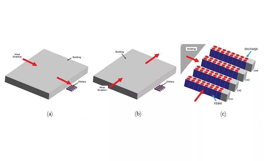
FIGURE 1. Schematic diagram of CFD models showing wind directions a) parallel, b) perpendicular to the air intakes (long dimension) of the chillers, and c) details of the chiller air intakes and discharge. (Source: Khankari, 2016)
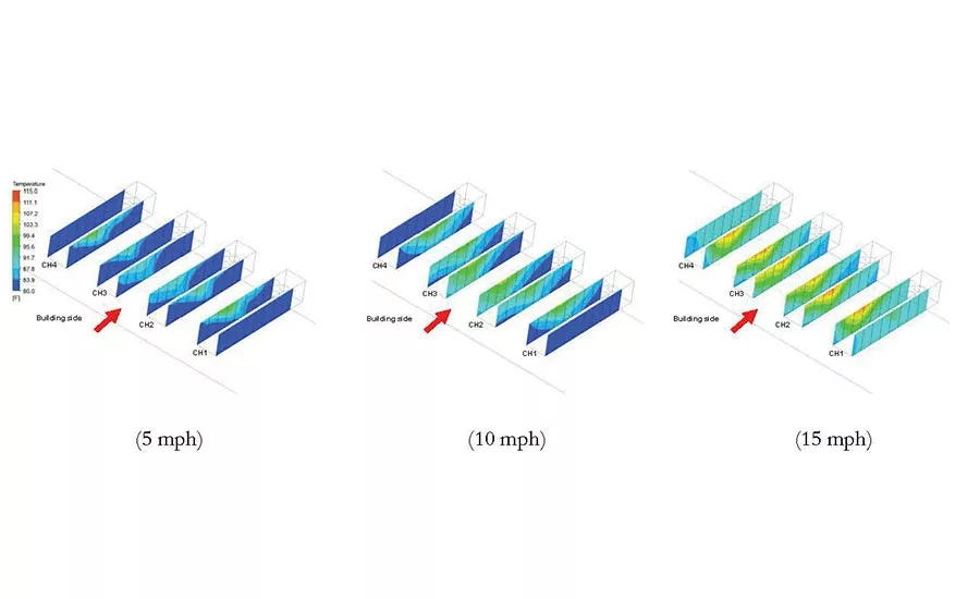
FIGURE 2. Effect of wind speed on the temperature distribution at the air intakes of chillers with parallel wind direction. Increase in the wind speed increases the intake air temperatures, which can potentially degrade the performance of air cooled chillers. The air intakes at the center of each chiller row show the highest rise in the air temperatures. (Source: Khankari, 2016)
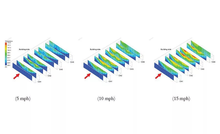
FIGURE 3. Effect of wind speed on the temperature distribution at the air intakes of chillers with perpendicular wind direction. The air intakes facing directly the incom-ing wind are least affected, whereas the subsequent air intakes show significant increase in the intake air temperatures. (Source: Khankari, 2016)
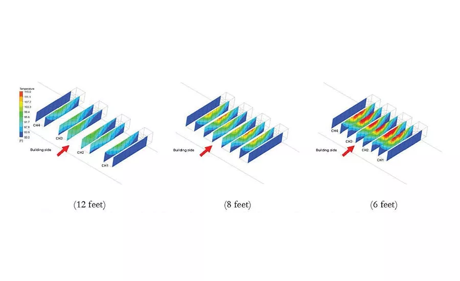
FIGURE 4. Effect of the spacing between the chillers on the temperature distribution at the air intakes of the chillers, showing intake air temperature increases as the spacing between the chillers decreases. (Source: Khankari, 2016)
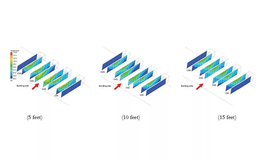
FIGURE 5. Effect of the distance of chillers from the building wall on the temperature distribution at the air intakes showing when chillers are moved away from the building the intake air temperature decreases. (Source: Khankari, 2016)
Ambient air is the primary heat rejection medium for the condenser coils of air-cooled chillers and dry coolers. Performance of air-cooled condensers can degrade under high ambient temperatures and windy conditions due to the recirculation of hot discharge plumes from the condenser fans into the chiller air intakes. Several factors including the wind speed, wind direction, chiller placement (i.e., distance between chillers, distance from building), and the height of the building and screen walls can affect the dispersion of discharge plumes from the chillers, which may lead to an increase in the temperature of air entering the air-cooled condenser.
For aesthetic reasons, these chillers are often placed behind architectural screens or placed at locations invisible to pedestrians, which can further restrict the flow of ambient air to these chillers. This can affect the performance of the air-cooled condensers. So, what is the ideal location for the air-cooled chillers? This study attempts to answer this question by investigating the impact of wind speed, wind direction (orientation of chillers with respect to wind direction), spacing between the chillers, and the distance of chillers from the adjacent building to determine the optimal location for air-cooled chillers.
VIRTUAL SETUP OF AIR-COOLED CHILLERS
A three-dimensional CFD model of a bank of four air-cooled chillers was developed for this analysis. As shown in Figure 1, the chillers are placed adjacent to a three-story, 40-ft high, 120,000-sq-ft building. Each chiller is equipped with a total of 16 fans arranged into two rows. The air intakes are located on each side of these chillers, and the discharge from the condenser fans is located on the top of the chillers.
The study analyzes wind directions parallel and perpendicular to the air intakes of chillers. Figure 1 shows the wind directions with respect to the orientation of chillers. These analyses were performed for three wind speeds (5, 10, and 15 mph); for two wind directions; for spacing between the chillers of 6, 8, and 12 ft; and for the three locations from adjacent buildings at a distance of 5, 10, and 15 ft. The study systematically investigated each parameter while keeping the other parameters constant.
EFFECT OF WIND SPEED
Increase in the wind speed results in an increase in the intake air temperatures, which can potentially degrade the performance of air-cooled chillers. Figure 2 shows the temperature distribution at the air intakes of chillers. In this case, when the wind direction is parallel to the air intakes, the chillers are located on the leeward side of the building, where a zone of low pressure is formed. With increase in the wind speed, the hot plume rising from the fan exhausts bends downward and entrains into the chiller intakes. In the case of low wind speed (5 mph), the hot plume rises vertically upward and away from the chiller intakes. As the wind speed increases from 5 mph to 15 mph, the discharge plume tends to bend downward and almost reaches the ground level in the case of 15 mph of wind speed, which promotes entrainment of hot plumes into the chiller intakes.
EFFECT OF CHILLER ORIENTATION
When the wind direction is perpendicular to the air intakes (long dimension) of the chillers, an increase in the wind speed also results in increase in the intake air temperatures (Figure 3). In this case, the front intake of the first chiller faces directly the incoming wind and as a result experiences the lowest intake air temperature. Since the other chillers are located in the wake zone (low pressure zone) of this first chiller, they experience higher intake air temperatures. While the hot discharge plumes flow in the direction of wind, the plumes from the windward side chillers move over the adjacent chillers, thus those plumes get entrained into the intakes of the leeward side chillers.
As shown in Figure 3, the effect of such cascading plume movement becomes prominent, with increasing wind speeds resulting in higher intake air temperatures especially for those air intakes located at the center of each row. Since the wind direction is perpendicular to the long dimension of the chillers, the ambient air can easily enter the chiller aisles from both front and back ends of the chillers. As a result, the temperature distribution on the chiller intakes is quite symmetric — high at the center and low at the front and back end.
EFFECT OF SPACING BETWEEN THE CHILLERS
The intake air temperature increases as the spacing between the chillers decreases. Figure 4 shows the effect of spacing between the chillers on the temperature distribution at air intakes of the chillers. When the spacing between the chillers is reduced, the ambient air does not reach the center of the chiller aisles, thus promoting the hot discharge plumes to entrain back into the air intakes. This is evident from the higher air temperatures at the top of the chiller intakes as shown in Figure 4.
When the chillers are placed apart at 12 ft, the hot discharge plumes are separated from each other and tend to move straight upward, resulting in lower intake air temperatures. When spacing is reduced, these plumes come close to each other and enter deep into the chiller aisles.
EFFECT OF DISTANCE FROM THE BUILDING
The intake air temperature increases as the chillers are placed closer to the building wall. Figure 5 shows the effect of distance of chillers from the building wall on the temperature distribution on the air intakes of chillers. When the chillers are placed closer to the building, they are moved further into the zone of low pressure. As a result, the hot discharge plumes from the chillers move towards the building and saturate the space between the building and the chiller, allowing for the hot air to enter the intakes located closer to the building.
Moving chillers away from the building allows the ambient air to enter from both ends of the chillers and helps in lowering the intake air temperature. However, this analysis indicates that the effect of increasing distance on the intake air temperature becomes less significant after 10 ft.
SUMMARY
A CFD study of a bank of air-cooled chillers adjacent to a three-story building indicates that higher wind speeds increase recirculation of discharge plumes into the chiller intakes, resulting in higher intake air temperatures. When the chiller intakes are oriented perpendicular to the prevailing wind direction, the discharge plumes from windward side chillers enter into the following leeward side chillers, and this cascading effect becomes prominent at higher wind speeds. This study further indicates that the spacing between the chillers has a larger impact on the recirculation of hot discharge plumes than the distance between the building and the chillers.
In real-world situations, the prevailing wind speeds and directions can vary significantly from location to location. Also, the terrain and surrounding structures can also affect the local wind speed and direction. Therefore, the extent of discharge plume recirculation can vary in each situation. Given the variability of these factors in real-world situations, CFD analyses can provide valuable insights in optimizing the orientation, spacing, and the distance of chillers from the adjacent buildings. Insights from this study indicate that placing the chiller air intakes parallel to the prevailing wind direction, with at least 10 ft spacing between the chillers, and at least 10 ft away from the adjacent building wall, may reduce the adverse recirculation of discharge plumes into the chiller air intakes and potentially improving performance. ES
REFERENCES
Khankari, Kishor. 2016. Optimum Placement for Air-Cooled Chillers. ASHRAE Journal. January 2016.
Looking for a reprint of this article?
From high-res PDFs to custom plaques, order your copy today!


