search
Ask ACHR NEWS AI
cart
facebook twitter instagram linkedin youtube
  • Sign In
  • Subscribe
  • Sign Out
  • My Account
  • NEWS
  • TECHNOLOGY
    • Heating & Boilers
    • Cooling & Chillers
    • Pumps & Flow Controls
  • SECTORS
    • Commercial
    • Health Care
    • Data Center
    • Educational Facilities
  • DESIGN | CONSTRUCTION
  • OTHER TOPICS
    • High-Performance Buildings & Automation
    • Ventilation and IAQ
    • Commissioning
    • HVAC Retrofits
  • TODAY’S BOILER
    • Today’s Boiler Archives
    • Today’s Boiler Digital Edition
  • MORE
    • Case Studies
    • Podcasts
    • Videos
    • Directory
    • Webinars
    • ES NEWS Store
    • White Papers
  • SIGN UP
  • Back to The NEWS
Engineered Systems NEWSHVAC Engineering TechnologyHVAC Engineering SectorsVentilation and IAQCommissioningHeating & BoilersCommercial HVAC

Commissioning Hydronic Unit Heaters

While these commonplace systems may seem simple, the variations and controls require attention.

By Rebecca T. Ellis, P.E.
Figure 1: Thermostat only

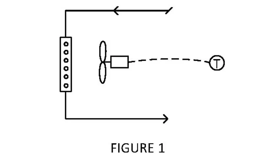
Figure 1: Thermostat only.

Figure 2: Thermostat and aquastat

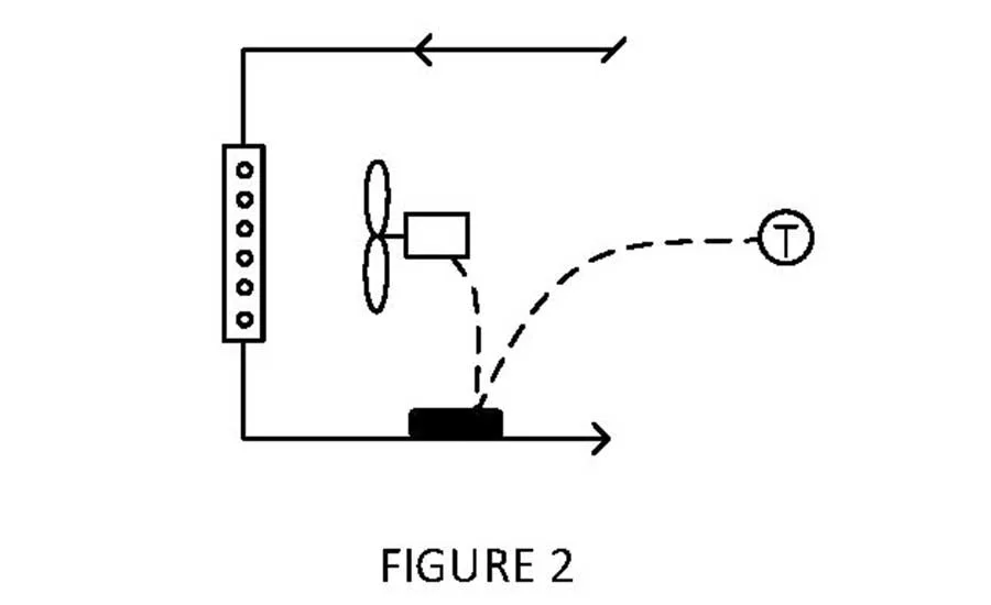
Figure 2: Thermostat and aquastat.

Figure 3: Thermostat, aquastat, and control valve

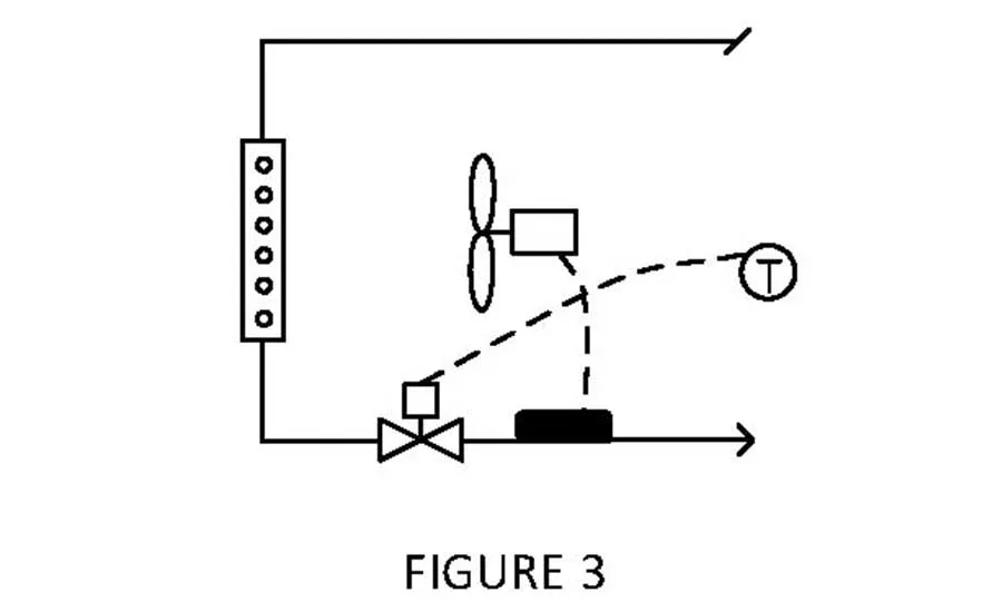
Figure 3: Thermostat, aquastat, and control valve.

Figure 1: Thermostat only
Figure 2: Thermostat and aquastat
Figure 3: Thermostat, aquastat, and control valve
January 3, 2017

This month, I am continuing my series on commissioning “simple” HVAC equipment with hydronic unit heaters. These are about as ubiquitous and low-tech as any equipment in a new building and, therefore, are prone to being nearly ignored by designers, contractors, and commissioning professionals.

Although simple, unit heaters are typically very important and used where the risk of freeze damage is high (e.g., vestibules, utility rooms, stairwells, loading docks). In addition to these devices needing to provide heat upon demand during cold weather, the design team may specify controls intended to minimize energy consumption when heating is not needed. Therefore, the commissioning professional must take them seriously during design review, controls integration, balancing, and testing.

Unit heater physical configurations are, by definition, almost universally the same: one fan drawing air from the conditioned space and pushing it through a heating coil back into the conditioned space. This month we are talking only about hydronic unit heaters, i.e., those piped to the building’s heating hot water system.

The unit heater elements that change from project-to-project are the controls. The figures illustrate three of the most common control schemes for hot water unit heaters.

Figure 1 is the simplest with a thermostat turning the unit heater fan on upon a call for heating and off when the thermostat is satisfied. The coil piping is open to the hydronic system and, if there is hot water flowing, the unit heater will deliver heat when the fan is on. If there is no hot water flow, the fan will run continuously without adding any heat to the space.

Figure 2 is the same as Figure 1 with the addition of an aquastat on the hot water return pipe. The aquastat senses whether there is hot water flowing through the unit heater coil and passes the thermostat call for heat to the fan only if the pipe temperature is above a certain set point. In this way, the fan only operates if there is a chance for the unit heater to actually heat the space. It is slightly more energy efficient than Figure 1.

Figure 3 is one of the most energy-efficient approaches to controlling hydronic unit heaters. A two-position control valve on the hot water pipe only opens upon a call for heat from the thermostat. Once hot water flow is sensed by the aquastat, a signal from the aquastat starts the fan. Of course, there could be other wiring strategies for these same components. The key to this strategy is only flowing hot water through the coil when it is needed, thus reducing both a negligible amount of pump energy and a significant amount of unnecessary radiation heat transfer from the coil. 

The commissioning professional needs to understand the intended unit heater operation during the design phase, verifying that the designers unambiguously define the control components and sequence of operation. Clearly, there are first-cost, performance, and operational cost implications with each of these three options. The commissioning professional will most likely be the team member to review these pros and cons with the owner. This can be a very brief conversation, but the design phase is the time to have it, not after the project is complete and the owner realizes these “little” items are not what the owner expected. ES

Share This Story

Looking for a reprint of this article?
From high-res PDFs to custom plaques, order your copy today!


Rebecca is president of Questions & Solutions Engineering, Inc. She can be reached at rteesmag@qseng.com

Recommended Content

JOIN TODAY
To unlock your recommendations.

Already have an account? Sign In

  • HVAC-enrollment

    The Trades Are Back: HVACR Programs See Nearly 30% Enrollment Spike

    A new wave of future technicians is entering the pipeline.  
    Training and Education
    By: Matt Jachman
  • 2025 Top 40 Under 40

    2025 Top 40 Under 40 HVACR Professionals List

    The 11th annual Top 40 Under 40 list highlights those...
    HVAC Commercial Market
    By: Hannah Belloli-Oster
  • LG Ductless Mini-Split Systems

    The 9 Types of Heat Pumps

    As the U.S. moves toward electrification, heat pumps are...
    Ground Source Heat Pumps
    By: Joanna R. Turpin

More Videos

Today's Boiler

Spring 2026 Issue

Today's Boiler - Spring 2026 Cover

Read More from Today's Boiler

Case in Point Logo

Smarter Hydronic Design for Data Centers - Free Webinar - January 22, 2026

Related Articles

  • Modine HotDawg Hydronic Garage Heater

    Hydronic Unit Heaters Provide Permanent Heat for Residential, Commercial Customers

    See More
  • Hazloc Heaters: Unit Heaters

    See More
  • Hazloc Heaters: Unit Heaters

    See More

Related Products

See More Products
  • Manual B.jpg

    Manual B - Balancing and Testing Air and Hydronic Systems

  • whpm.png

    Water Heaters

  • Modern Geothermal HVAC Engineering and Control Applications

See More Products

Related Directories

  • Camus Hydronics Ltd.

    Camus Hydronics is a complete boiler room solutions provider that manufactures an extensive line of gas fired high-efficiency copper tube and stainless-steel boilers for commercial/industrial applications.
×

Sign Up. Stay Informed.

The #1 trusted source for the HVACR industry since 1926

SUBSCRIBE
  • RESOURCES
    • Advertise
    • Contact Us
    • Advisory Board
    • Classifieds
    • Submit a Letter
    • Directories
    • Store
  • ACCOUNT CENTER
    • Create an Account
    • Start a Subscription
    • Manage My Account
    • Sign Up for Newsletters
    • Visit Customer Service
    • Update Preferences
  • SERVICES
    • Marketing Services
    • Reprints
    • Market Research
    • List Rental
    • Survey/Respondent Access
  • STAY CONNECTED
    • LinkedIn
    • Facebook
    • Instagram
    • YouTube
    • X (Twitter)
  • PRIVACY
    • PRIVACY POLICY
    • TERMS & CONDITIONS
    • DO NOT SELL MY PERSONAL INFORMATION
    • PRIVACY REQUEST
    • ACCESSIBILITY

Copyright ©2026. All Rights Reserved BNP Media, Inc. and BNP Media II, LLC.

Design, CMS, Hosting & Web Development :: ePublishing