Successful Smoke Control: Caution & Coordination
This second look at the Museum Of The Bible project focuses on the integrated life safety design approach. The team arrived at a final design that not only provides functionality appropriately tailored to the space but also incorporates itself into architectural elements to preserve aesthetic value. The BAS plays a key role between the mechanical and electrical sides of smoke control as well.

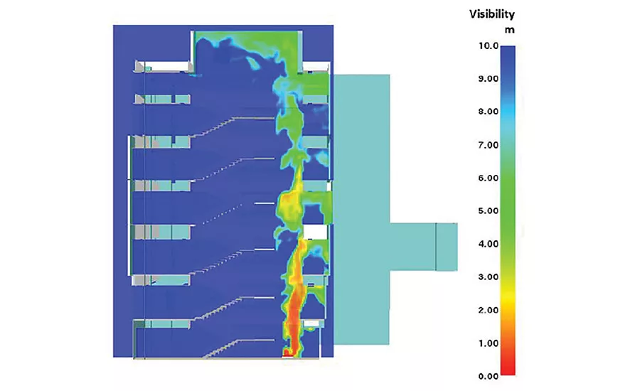
FIGURE 1. N-S section looking east – fire scenario at B1 Level. Visibility to a normal object at 20 minutes
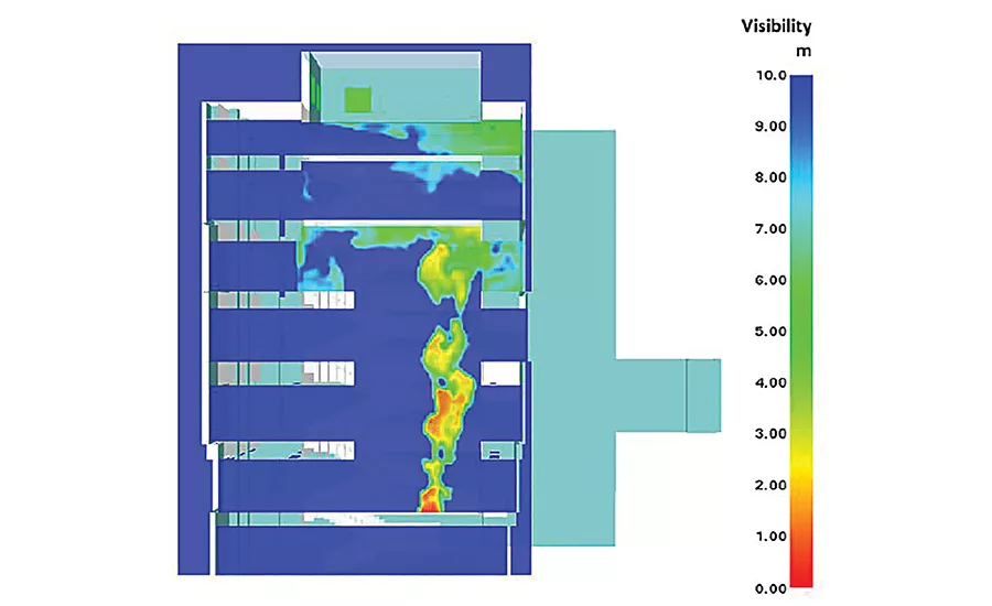
FIGURE 2. N-S section looking east – fire scenario at 01 Level. Visibility to a normal object at 20 minutes. (Life Safety Narrative and images courtesy of Hughes Associates.)
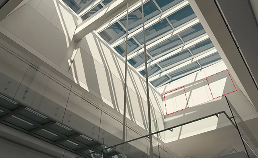
FIGURE 3. Atrium skylight.
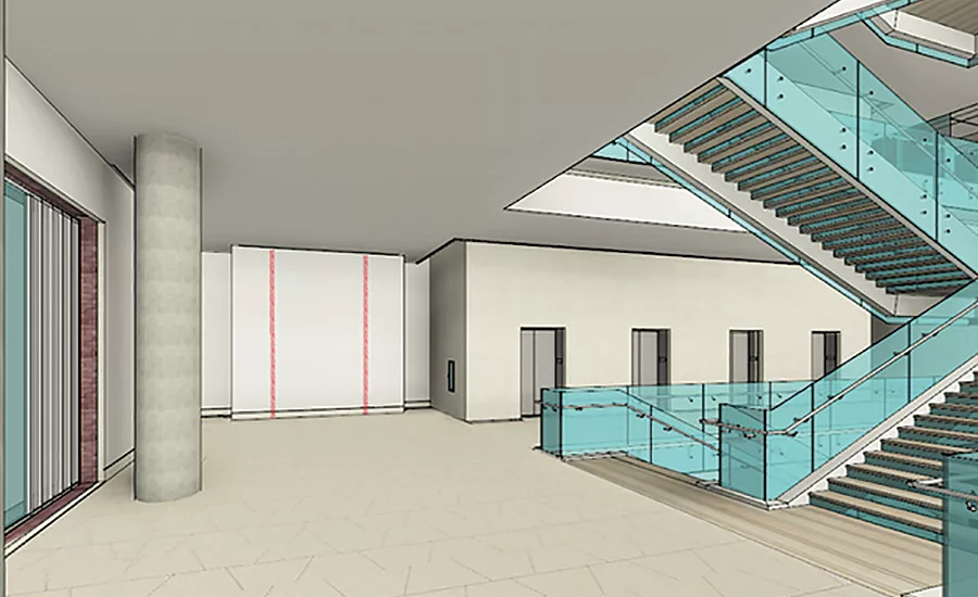
FIGURE 4. Location of the atrium make-up air doors on the first floor.
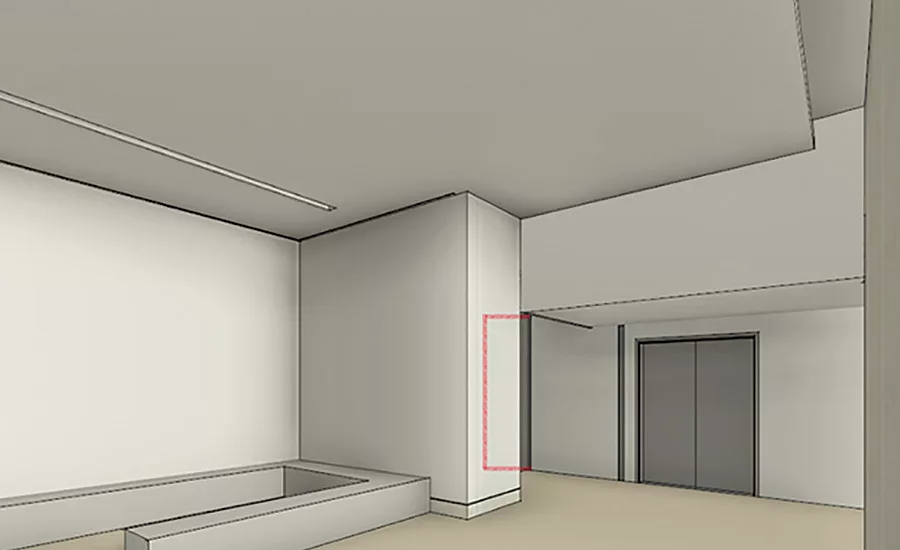
FIGURE 5. Location of the atrium make-up air doors on a typical floor.
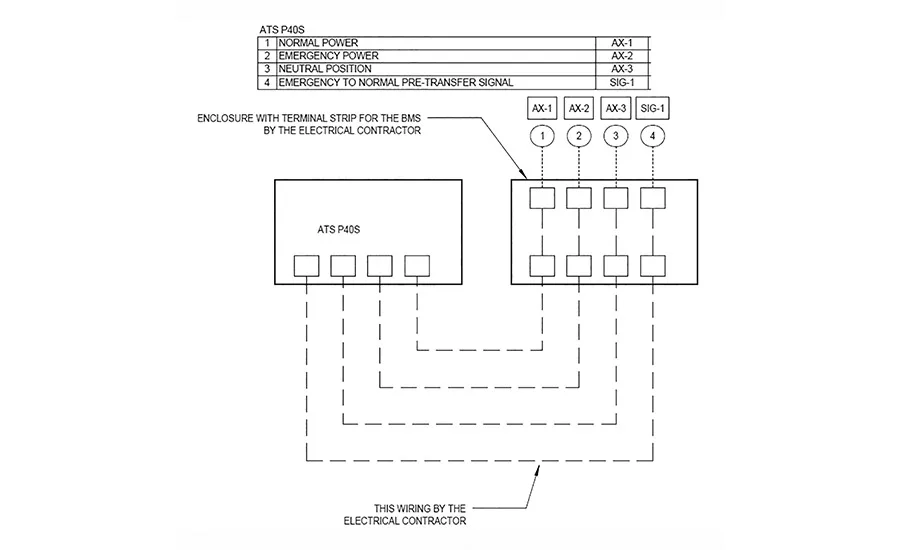
FIGURE 6. Monitoring of the open transition automatic transfer switches by the BAS.
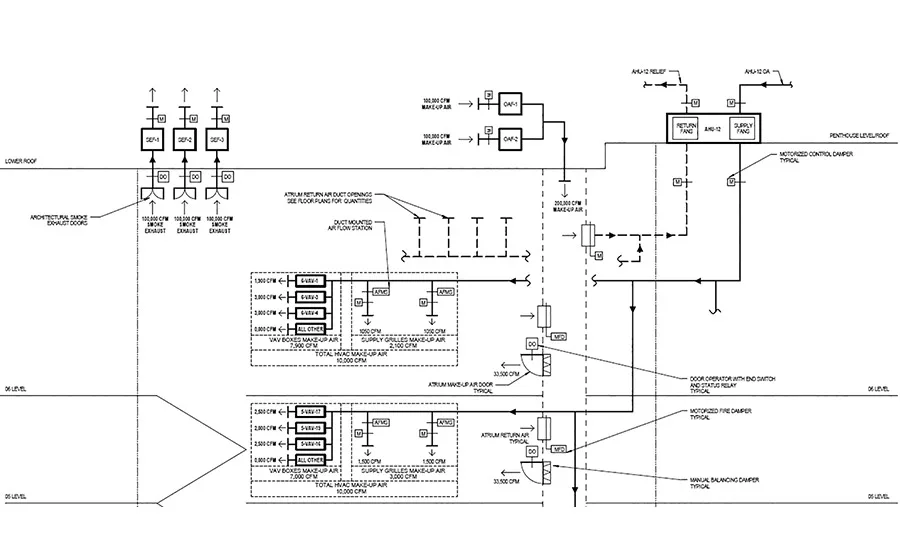
FIGURE 7. Fifth- and 6th-level atrium smoke exhaust system.
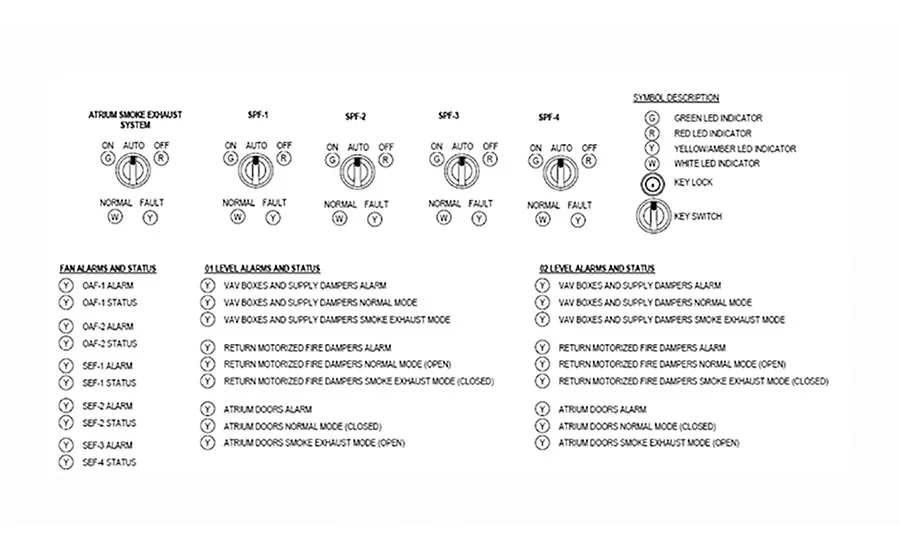
FIGURE 8. Alarms and keyed switches at the FSECP.
The Museum of the Bible (MOTB) will be a non-sectarian museum focusing on the history and impact of the Bible with a core collection of more than 40,000 biblical antiquities and rare biblical texts and artifacts. The museum will contain a mix of uses, including exhibit space, library resources, meeting spaces and guest rooms for visiting scholars, space for certain affiliated museums and their exhibits, and sound ground floor accessory retail uses, such as a gift shop and café or food service establishment.
The Museum of the Bible will be a six-story building with two stories below grade located in Washington. Along the northeast side of the building, a monumental stair will span the B1 through 6th Levels creating a seven-story atrium. The skylight located above the atrium opening will serve as a smoke reservoir where smoke will be extracted upon activation of the atrium smoke exhaust system.
Due to the height of the atrium, and in accordance with the International Building Code, a mechanical smoke exhaust system intended to provide a tenable environment for the evacuation or relocation of occupants had to be designed.
Due to construction constraints and to minimize the probable impact of the smoke exhaust system components on the building architecture, the design team chose not to follow the code-related prescriptive requirements when designing and sizing the smoke control system. Instead, a specialized consulting firm was employed to perform a CFD model utilizing a Fire Dynamics Simulator (FDS) to size the overall capacity of the smoke exhaust system, as allowed by and in conformance with applicable code requirements.
Due to the complexity of the smoke exhaust system and of the architectural design intent for the atrium, the integrated design team, in line with its own integrated design standards, designed the smoke exhaust system such that all systems not only will operate in a seamless and integrated approach but, from an architectural perspective, the smoke exhaust system will be fully integrated with the architectural elements of the atrium.
Life Safety and Computational Fluid Dynamics Design Approach
The CFD analysis evaluated the impact of a fire in the atrium resulting in an axisymmetric and balcony spill plume scenario. In the context of the Museum of the Bible atrium, a fire resulting in a balcony spill plume could occur in the low-ceiling areas adjacent to the atrium opening. In this scenario, smoke generated from the fire would form a ceiling jet on the underside of the ceiling and flow towards the atrium opening where it would spill into the atrium opening and rise to the top of the atrium. An axisymmetric fire scenario could only occur in a location beneath the atrium opening. In the Museum of the Bible atrium, that axisymmetric fire could only occur beneath the atrium opening on the B1 Level and Level 1.
An evaluation of the atrium geometry and anticipated fuel loading was performed to develop conservative design fire scenarios for the analysis. For the axisymmetric fire scenarios, fast growth fires reaching a peak heat release rate of 2,000 kW were evaluated based on the anticipated uses and combustible contents that would be in the atrium. In the case of balcony spill fire scenarios, the peak heat release rate of the fire was determined based on the time sprinklers above the fire were calculated to activate. On the B1 Level, the analysis showed that sprinklers would activate at a fire size of about 800 kW (Figure 1). On Level 1, the analysis showed that sprinklers would activate when the fire reached about 1,500 kW (Figure 2).
The analysis included 300,000 cfm of exhaust being drawn from three exhaust outlets installed in the skylight. Makeup air at 260,000 cfm was then modeled as being provided on Levels 1–6 from the northeast makeup air shaft and ceiling-level supply terminals. Air from the northeast makeup air shaft will be provided at up to 400 fpm from makeup air doors on Levels 1–6. The analysis evaluated the impact of introducing makeup air at 400 fpm from these locations and demonstrated that the increased makeup air velocity would not impact the ability of the atrium smoke control system to maintain tenable conditions in the atrium for 20 minutes.
Architectural Design Approach
Three doors located at the north and east sides of the atrium skylight aperture connect to the atrium smoke exhaust fans on the roof. A delay was built into the operating sequence in order to ensure that the doors reach their fully open positions before the system starts (otherwise the door openers would be fighting against the suction of the fans). Flush-mounted, insulated frames with concealed hinges were selected allowing the assemblies to blend with the surrounding walls. The architects chose to establish a grid of vertical reveals based on the module of one door leaf on all four surfaces, creating a subtle pattern that adds depth and texture to the space.
Given the limited available opening area on the facades, a 10- by 10-ft vertical shaft running the full height of the building was designed to supply makeup air from above to each atrium level. On the ground floor, after transitioning horizontally over the staff entrance ramp, the makeup supply is incorporated behind a floating, full-height art wall, with custom 12-ft tall doors hidden in recesses on either side of the offset partition.
At the upper levels, the architects wanted to find space in the atrium plan for a built-in seating corner (essentially an ‘L’ shaped nook), and the preferred location ended up being directly across from the supply doors from the makeup shaft. Although the team was initially concerned that this design element would partially block the flow of air and negatively affect the performance of the CFD model, through consultation with Hughes Associates and the mechanical and life safety engineers, it was determined that the seating elements actually help slow down the makeup air supply velocity. The air enters the main volume of the atrium at a more manageable speed, permitting smaller doors than originally anticipated to be used.
Electrical Design Approach
All the controls for the atrium smoke exhaust system are done through the BAS.
The atrium smoke exhaust system and all related life safety and mechanical systems were designed to have two sources of power. The primary power is from the normal building power systems.
The secondary power source is comprised of a total of eight natural gas fired generators located in the penthouse of the building and separated from the normal power transformers and switch gears. The transfer from the primary source of power to full standby power was designed to be automatic and within 60 seconds of failure of the primary power.
All mechanical and control systems that are intended to operate during the operation of the atrium smoke exhaust system are also provided with two sources of power. Due to the requirements imposed by the local utility company, closed transition automatic transfer switches were prohibited from being used on the project. As such, open transition automatic transfer switches are used to switch between the two sources of power.
Most of the open transition transfer switches provide a “break-before-make” switching action: the contact for the connected power source has to be open before closing the contact for the new power source; this will cause a total power interruption for a short period of time. This switching action can directly affect how the atrium smoke exhaust system is operating; if the building loses the primary source of power, during the switchover to the secondary power source, the atrium smoke exhaust fans and all other related systems will also lose power, even if temporary.
To ensure that the mode of operation of the open transition automatic transfer switches does not affect the operation of the smoke exhaust system, the status of each automatic transfer switch had to be monitored by the BAS.
Each automatic transfer switch is provided with four control points, which the BAS monitors:
Normal power. The automatic transfer switch is operating under the primary power source.
Emergency power. The automatic transfer switch is operating under the standby power source.
Neutral position. The automatic transfer switch is in the neutral position; this can occur either during the transition process or in case of overloading.
Emergency to normal transfer signal. This built-in time delay function is used to notify the BAS that normal power is available and that the mechanical equipment served by the automatic transfer switch will soon lose power as the switch will transfer to the primary power source.
In addition to the challenges created by the operation of the open transition automatic transfer switches, the design team had to account for the way in which the generators are not just operating but also tested. Each time the generators will be tested, it will cause the automatic transfer switches to switch to the secondary power source; this in turn, as described above, can affect the operation of the atrium smoke exhaust system.
The generator control system was designed to allow the operator the control their testing via two switches: START and STOP. In addition, an “INHIBIT SIGNAL” is used by the BAS to control if the generators should or should not stop their current mode of operation. The intent of this approach is to allow the mechanical control systems that are a part of the atrium smoke exhaust system to “react” and to ensure that the functionality of the smoke exhaust system is not affected.
Mechanical Design Approach
All components of the smoke exhaust system are controlled by the BAS; however, all commands come from the Fire Alarm Control Panel (FACP) and/or the Fireman’s Smoke Exhaust Control Panel (FSECP).
Testing of the various components of the smoke exhaust system is done locally at the FSECP, while the full automatic activation of the smoke exhaust system is done by the FACP.
The atrium smoke exhaust system comprises the following: three exhaust fans, two outside air fans, one AHU, air terminal units (VAV boxes), atrium doors, and various motorized fire dampers.
The two outside air fans provide approximately 67% of the makeup air, while the remaining 20% is provided by a dedicated air handling unit.
During the “normal” mode of operation, the AHU will cool and heat the atrium spaces and various gathering type spaces on the top floor. A return air shaft is used to return the air from the atrium floors back to the AHU.
Upon activation of the atrium smoke exhaust system, the AHU becomes a 100% outside air unit and the return air shaft becomes a makeup air shaft. In addition, all air terminal units connected to the AHU supply duct system that serve the atrium will switch to a “makeup air” mode while all other air terminal units shut down; each floor will then receive a predetermined amount of makeup air from the air terminal units and related supply air terminals.
The status of all atrium smoke exhaust system components is displayed at the FSECP. In addition, the testing of the various components of the smoke exhaust system, including stair pressurization fan, can be performed at the FSECP via keyed switches located on the FSECP.
Conclusion
Although smoke exhaust systems can vary in complexity and mode of operation, their main purpose is life safety. An integrated design team with an integrated design approach succeeded in making the atrium smoke exhaust system for the Museum of The Bible successfully achieve more than just its main purpose; its architectural features makes it “hidden” to the building occupants without compromising functionality. ES
The authors would like to thank Marc Hodapp and Hughes Associates for performing the CFD analysis, completing the related report, and providing recommendations to the design team.
Looking for a reprint of this article?
From high-res PDFs to custom plaques, order your copy today!


