Optimizing Airflows In Foodservice Facilities Part 1- Optimizing Entering Air-flows

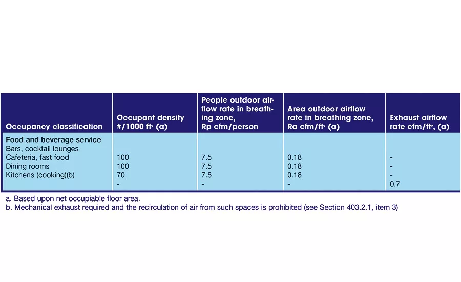
Table 1. Excerpts of outdoor airflow requirements in 2012 IMC Table 403.3.1
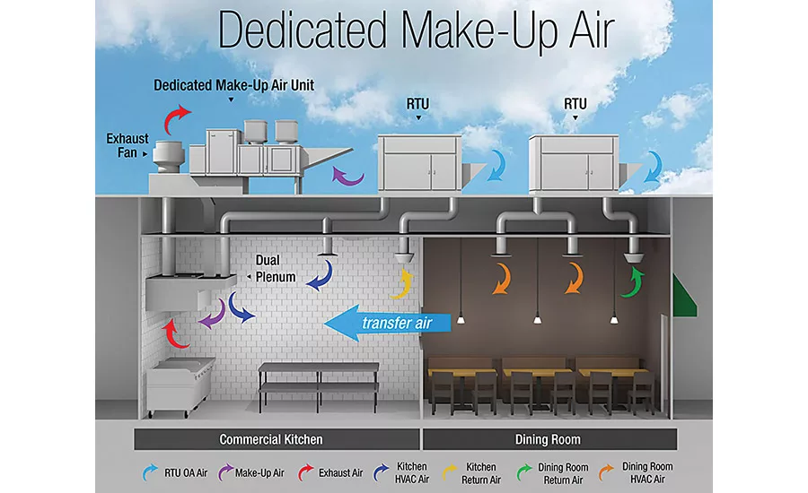
Figure 1. Ventilation system schematic with dedicated makeup added.

Table 2. Surveyed seating occupancy factors.
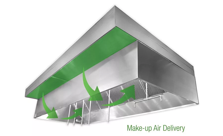
Figure 2.Wall canopy hood with single plenum perimeter makeup air distribution device.
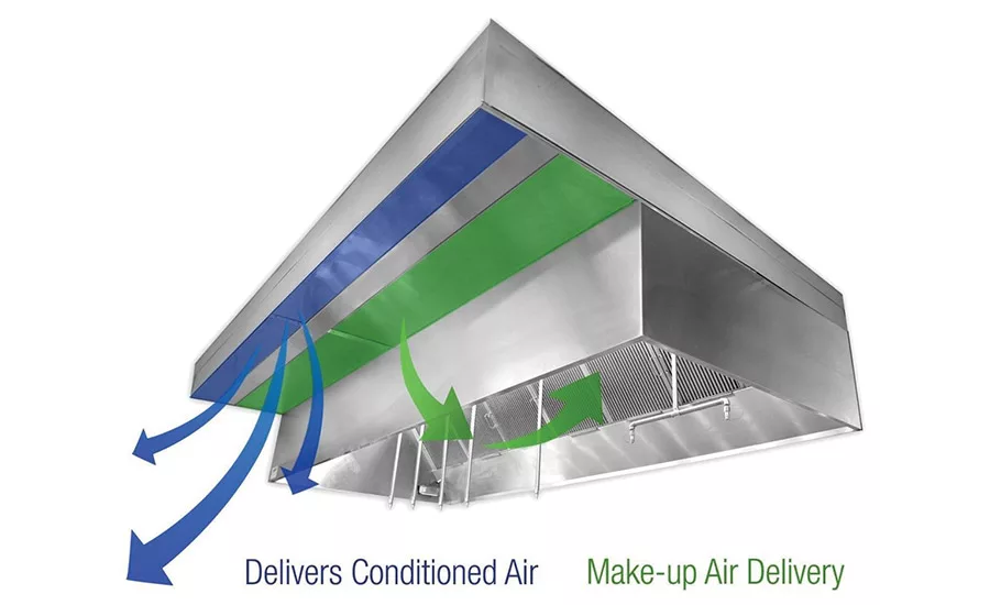
Figure 3. Double plenum makeup air distribution device.
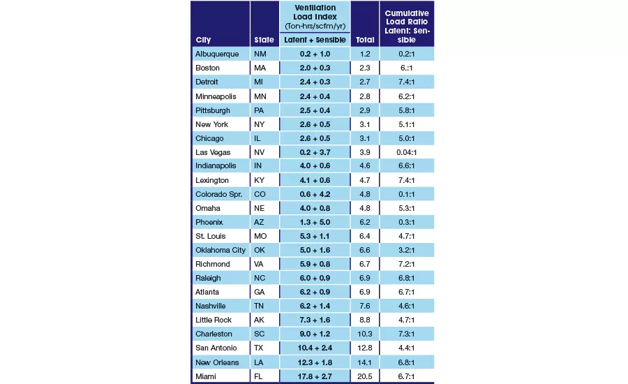
Table 3. Ventilation Load Indices (VLI) for selected continental U.S. locations.
Designs of mechanical systems for commercial foodservice facilities such as restaurants must comply with code requirements for outdoor air, as well as providing makeup air to compensate for typically large amounts of air exhausted from kitchens. Depending on locations and designs, heating and cooling of outdoor air that is used quickly to replace exhausted air is often costly.
Part 1 of this series offers suggestions for optimizing entering airflows for foodservice facilities, including:
- Using reduced outdoor air requirements in recent code editions;
- Calculating estimated occupancies with realistic seating factors;
- Specifying RTU heating and cooling capacities for local climates;
- Eliminating airflows that reduce exhaust hood performance;
- Using dedicated makeup air for kitchen exhaust when possible; and
- Optimizing dedicated makeup air distribution.
Optimizing Code Required Outdoor Airflow
Codes and standards require minimum amounts of outdoor air to be brought into foodservice facilities based on facility space sizes and occupancies. Recent code editions generally require less outdoor air than older editions.
Some foodservice facility mechanical designs provide all required outdoor air through rooftop units, tempering this air to nominal space temperatures, such as 70°F for heating and 75°F for cooling. Energy conservative designs call for furnishing some of the outdoor air through rooftop units, and when possible, furnishing some outdoor air through dedicated makeup units, which typically heat and cool makeup air to less than nominal space conditions, depending on local climate conditions.
For foodservice and other commercial facilities in the U.S., the International and Uniform Mechanical Codes (IMC and UMC) specify outdoor air requirements in harmony with ASHRAE Standard 62.1 — Ventilation for Acceptable Indoor Air Quality. Plan reviews and enforcement, of course, depend on which code and standard editions are adopted by local code jurisdictions.
Outdoor air requirements for foodservice facilities in older mechanical code editions were 15 cfm per kitchen occupant, 20 cfm per dining room, cafeteria, and fast food occupant; and 30 cfm per bar and cocktail lounge occupant. Table 1 shows relevant excerpts from IMC 2012 Table 403.3, with significantly reduced requirements for outdoor airflows per occupant, though an airflow requirement per ft² of occupiable area is added, and a minimum kitchen exhaust rate is specified. UMC Table 4-1 requirements are numerically identical.
Case Study
A simple case study, based on plans for a nationwide chain of casual dining restaurants, illustrates a typical reduction in required outdoor air requirements in older and newer code editions. Using real design parameters, the chain’s estimated occupancies in the bar, dining room, and kitchen are 60, 138, and 19, respectively. These estimated occupancies take advantage of a longstanding exception to IMC section 403.3, as discussed below, instead of using occupant densities shown in column two of the table.
Old Method. Required outdoor air.
Bar: 60 x 30 cfm/person = 1,800
Dining: 138 x 20 cfm/person = 2,760
Kitchen: 19 x 15 cfm/person = 285
4,845 cfm
New Method. From column three, people outdoor airflow is 7.5 cfm per person for bar and dining room. From column four, area airflow is added, at a rate of 0.18 cfm/ ft² for net occupiable areas of the bar (950 ft²) and dining room (1,970 ft²), but not the kitchen area. The required outdoor air is:
People Airflow
( bar 60 + dining 138 = 198) persons x 7.5 cfm/person = 1,485 cfm
Area Airflow
(Bar 950 + Dining 1,970 = 2,920) ft² x 0.18 cfm/ ft² = 526 cfm
Required outdoor airflow = People + Area airflows = 1,485 + 526 = 2,011 cfm
With current code editions, the outdoor airflow requirement is 2,011 cfm, compared to 4,845 cfm from older code editions, a reduction of 58%. As a result, heating and cooling of outdoor air can be reduced by the same percentage if the outdoor air is tempered to the same conditions. The kitchen exhaust calculated from column five is not relevant to the outdoor air comparison if the exhaust is greater than required outdoor air.
Depending on the kitchen exhaust rate, reduced outdoor airflow to the dining room can enable greater use of dedicated makeup air for the kitchen exhaust, such as configured in Figure 1. The dual plenum makeup air device shown in Figure 1 is described later in this article.
Occupancy and Seating Factors. Required outdoor airflow can also be reduced by using realistic estimated occupancies, taking advantage of an important, longstanding exception to the requirements IMC Table 403.3:
“The occupant load is not required to be determined based on the estimated occupant load rate indicated in Table 404.3 (column two in Table 1 above) where approved statistical data document the accuracy of an alternative anticipated occupant density.”
While it’s tempting to estimate anticipated occupant density by counting seats in a foodservice facility, a yearlong survey of actual occupancies in over 100 restaurants by ASHRAE Life Member Gerrit S. van Straten, P.E., found that actual occupancies are considerably less than seat counts, even at busy times.² Significantly, customers do not conveniently arrive in groups of one, two, three, four, etc., to completely fill available tables with one, two, three, four, etc. seats. Van Straten’s survey provides realistic occupancy estimates of people per table size:
Total estimated occupancy is the sum of the number of tables of each size multiplied by the corresponding occupancy factors. According to van Straten, the average occupancy of the 100+ sample restaurants during busy hours was about 65% of the seat counts. A similar survey, known by the author and conducted by a large quick service restaurant chain in the late 1980’s, coincidently found average occupancy of 65% for the chain’s typical dining rooms with mostly four seat tables and booths.
From his experience using the survey’s seating factors in restaurant designs, van Straten concluded:
- Counting seats in dining rooms overstates actual occupancies and increases outdoor air beyond the intent of codes;
- Outdoor ventilation rates calculated using the seating factors provide healthy, comfortable restaurants; and
- Code officials in several states approved restaurant projects using the survey’s seating factors, agreeing that the intent of ventilation code requirements were satisfied.
Optimizing RTU Cooling Capacities for Climates
RTU Capacity and Ventilation Load Index. Optimizing airflows also means providing desired air temperatures. Because of typically large amounts of air needed to compensate for exhaust air, it’s important to correctly specify RTU heating and cooling capacities.
The breakthrough Ventilation Load Index (VLI) concept was developed and published by Harriman, Plager, and Kosar in their article selected as the best ASHRAE Journal article for 1997.3 Derived from climate data, the VLI is a two-part index of latent and sensible loads, in ton-hours per cfm per year. The center column in Table 3 provides the two-part indices for 24 sample cities in increasing order of total load.
RTU cooling removes both latent and sensible loads, so it’s important to know the latent and sensible ratios, as well as total cooling loads, for the areas in which RTUs will operate. With greater latent loads, RTU sensible cooling is reduced, and vice versa, though the tradeoff is not linear.
Most surprising is the variation among the 24 sample cities, from 0.2 + 1 for Albuquerque, NM, to 17.8 +2.7 for Miami, FL. The latent load in Albuquerque is about 1/5 the sensible load, with a total of 1.2, while Miami’s latent load is 6.7 times greater than its sensible load, and its total load of 20.5 is the highest of the 24 sample cities. The right-hand column of Table 3 provides the ratios of latent to sensible loads for the sample cities.
The authors summarize their article by stating: “Examination of typical behavior of weather shows that latent loads usually exceed sensible loads in ventilation air by at least 3:1 and often as much as 8:1. A designer can use the engineering shorthand indexes…to quickly assess the importance of this fact for a given system design.” From this research, data for over 200 cities was added to chapter 24 of the ASHRAE Handbook of Fundamentals.
Utilizing Dedicated Makeup Air
In restaurants in which exhaust airflow exceeds the required outdoor airflow, including use of van Straten’s seating occupancy factors, designers frequently specify the use of dedicated makeup air provided by dedicated rooftop makeup air units. Unlike conventional RTUs, and depending on designs for different climates, dedicated makeup units can be designed for moderate heating or cooling of 100% of outside air delivered. Depending on conditions, savings result when makeup air is untempered or partially tempered, particularly if delivered by efficient, low-velocity distribution devices close to exhaust hood entrances.
Research on Makeup Air Delivery Devices
Reference 4 reported on studies of several hood makeup air methods and devices. Tests of each device with a standard wall canopy hood confirmed the inefficacy of hood front face and air curtain diffusers; as well as back wall and short-circuit makeup methods. In each test, these makeup devices interfered with hood performance if more than small amounts of makeup air were provided, for reasons particular to each device.
From testing and experience, use of these devices has diminished greatly, except that many are still installed in thousands of commercial kitchens, where they are negatively affecting exhaust hood performance. Some, such as air curtain, face discharge, and short-circuit designs can be retrofitted with more efficient devices.
Four-way diffusers are often used in restaurant designs, including in kitchen areas near hoods. Tests in Reference 4 showed negative effects on hood performance if more than 15% of the exhaust rate was made up with a four-way diffuser 2 ft away from the front center of a test hood. Four-way diffusers near hoods can easily be replaced with single- or double-perforated supply diffusers to improve hood performance. According to Reference 4, the key to using ceiling diffusers is keeping air velocities at hood entrances 50 fpm or less.
Optimizing Dedicated Makeup Air Distribution
In comparison to the ineffective methods discussed above, two modern, similar makeup air delivery devices are highly effective, as verified by manufacturer testing and successful use in thousands of restaurants.
The first device features a rectangular plenum mounted about 18 in above the lower front edge of a wall canopy hood, along the full length of the hood, as shown in Figure 2. The device delivers dedicated makeup air that is untempered in some climate areas and partially tempered in many other climate areas, such as heating to 55°F and cooling when outdoor temperature is above 85°F.
Figure 3 illustrates the second makeup air distribution device, which builds upon the first device by adding an outer plenum to deliver air tempered to space conditions, such as from a standard RTU. In typical installations, this air would previously have been distributed by high-velocity four-way diffusers near the hood, with negative effects on the hood.
To prevent condensation from cooled air, the inner and outer plenums are separated by insulation. In both products, air is distributed downward through two layers of perforated stainless to spread out the airflow. Downward airflow velocities from the plenums are specified to aid hood performance.
Summary
Newer editions of the IMC, UMC, and ASHRAE 62.1 require less outdoor air for foodservice facilities than older editions. In addition to reducing RTU size and fan energy, this usually results in less heating and cooling of outdoor air. As allowed by the exception to IMC section 403.3, realistic restaurant occupancies can be approved with relevant data, such as the seating factors provided in a study by Gerrit van Straten. Breakthrough research and calculations by Harriman et al have provided both latent and sensible load cooling loads for 200 continental U.S. cities. With this data available in the ASHRAE Handbook of Fundamentals, engineers can better match RTU capacities with local climate conditions.
To the extent that planned hood exhausts from foodservice facilities exceed outdoor airflows required by codes, energy can be saved by using dedicated makeup units with highly efficient distribution devices. While many customary makeup air distribution devices have been shown (in Reference 4) to negatively affect hood capture performance, products are available to efficiently deliver low-velocity untempered or partially tempered makeup air to hoods, while simultaneously delivering low-velocity fully tempered air to kitchen areas near the hoods.
In next month’s issue, part 2 of this series will cover optimizing exiting airflows, mainly from kitchen exhaust hoods, with a brief review of sponsored research and recommendations for passive and active means of reducing these airflows. A simple makeup air velocity theory will help explain differences in exhaust hood designs. ES
References
1. Table 403.3 excerpted from the 2012 International Mechanical Code; copyright 2011. Washington, D.C.: International Code Council. Reproduced with permission. All rights reserved. www.ICCSAFE.org.
2. van Straten, G. S. “Occupancy Formula – a New Method for Calculating Alternate Food Service Dining Room Occupancy.” Publication Pending.
3. Harriman, L. G., et al. “Dehumidification and Cooling Loads from Ventilation Air” ©ASHRAE, www.ashrae.org. ASHRAE Journal, November 1997
4. Brohard, G. et al. “Makeup Air Effects on Commercial Kitchen Exhaust System Performance.” Public Interest Energy Research. California Energy Commission, Sacramento, CA, 2002.
Image Credits:
Figures 1-3 courtesy of CaptiveAire Systems, Inc.
Looking for a reprint of this article?
From high-res PDFs to custom plaques, order your copy today!