An Unsettled Science: Finding The Design Basis For VAV Fume Hood Exhaust Airflow
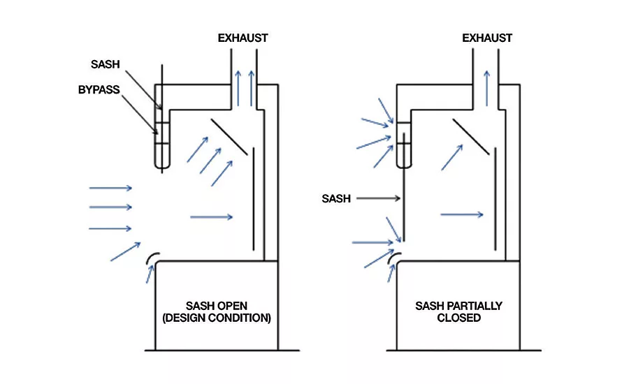
Figure 1. VAV fume hood concept.

Table 1. Fume hood exhaust guidance in industry standards.

Figure 2. Diffuser throw information describing length of 50-fpm terminal velocity throw. (Used with permission from Krueger.)
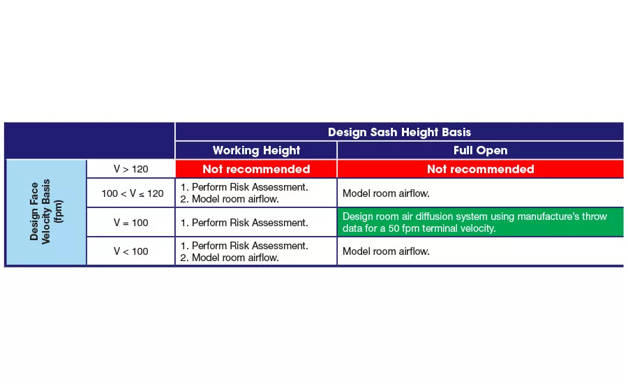
Table 2. Basis validation requirements.
VAV laboratory fume hoods have dominated the laboratory design world for the last 25 years. Conventional wisdom suggests that the specification of the design exhaust flow rate for them is an established rule, but in fact, it is not. The method for specifying exhaust airflow varies depending on the engineer’s experience, owner’s standards, and industry guidance through consensus standards. This article summarizes the available knowledge on this subject and prescribes an approach to establishing the design exhaust airflow from a laboratory fume hood.
A broad design basis can be used as a starting point:
The design exhaust airflow from a VAV fume hood is the flow required to create a safe environment to perform research within its confines.
Anyone who has experience in designing HVAC systems for laboratories is familiar with the VAV concept. A VAV hood maintains a constant face velocity throughout the sash movement by varying the hood’s exhaust airflow. The design flow rate will be the maximum flow through the hood (Figure 1).
The exhaust airflow through a VAV fume hood is defined by the following relationship:
Q=V×A
Where:
Q = Fume hood exhaust airflow, cubic ft per minute (cfm)
V =
Average fume hood face velocity across the face, ft per minute (fpm) — henceforth, referred to as face velocity
A = Fume hood face area, ft2
The complications in establishing the design basis arise from the many choices for the two variables in this equation — face velocity and face area. Does the basis assume a 100 ft per minute (fpm) face velocity? Or is it 80 fpm, or lower? Maybe higher? Does the design flow rate assume the face area at the full open sash height or some other “working” height?
If the basis for establishing the fume hood exhaust flow is questioned than the capacity of the HVAC system dedicated to the laboratory comes into doubt. Therefore, a critical element in the design process for laboratories is establishing a correct basis for this parameter.
Laws and standards
The search for answers begins with a review of the legal requirements related to the laboratory environment. In the U.S., Federal regulation 29 CFR 1910.1450, OSHA Laboratory Standard, provides direction.i This law applies to all employers engaged in the laboratory use of hazardous chemicals. Because a fume hood typically resides in a laboratory handling hazardous chemicals, this regulation applies to most situations involving a fume hood. The mandatory language in the law specifies:
“§(e)(3)(iii) A requirement that fume hoods and other protective equipment are functioning properly and specific measure that shall be taken to ensure proper and adequate performance of such equipment.”
The lack of specificity in this wording is deliberate. The law recognizes that no single approach can apply to every case. The non-mandatory Appendix A, offers additional guidance:
“§(C)(4)(g) General air flow should not be turbulent and should be relatively uniform throughout the laboratory, with no high velocity or static areas; airflow into and within the hood should not be excessively turbulent; hood face velocity should be adequate (typically 60-100 lfm)”
The language of the rule suggests that the design basis must be defined by the specific needs of the laboratory and not on a “universal” prescriptive design standard.
Building Codes are similarly vague in their guidance. For example, the International Mechanical Code states:
“Hoods or enclosures shall be used where contaminants originate in a limited area of a space. The design of the hood or enclosure shall be such that air currents created by the exhaust systems will capture the contaminants and transport them directly to the exhaust duct.”ii
The search for answers continues with the review of the standard of care surrounding laboratory design. This is embodied in several industry standards summarized in Table 1.
From Table 1, the reader finds no prescriptive solution for defining the exhaust airflow from a VAV fume hood. All of the recommendations require judgment from the design team. Thus, neither law or industry standards provide a simple paradigm for specifying this value. However, these documents hint at a design basis. First, a range of face velocities offers the best performance. Velocities outside of this range adversely affect hood performance. Second, maintaining a low turbulence environment at the hood face improves hood performance, which is measured by the ability of the hood to capture and remove the fugitive emissions generated by the experiment in the hood. These characteristics define the ability of the hood to “contain” the hazardous emissions generated in it.
Because containment of emissions is the intent of the hood, the aforementioned fume hood exhaust airflow design basis is restated:
The design exhaust airflow from a VAV fume hood is the flow required to produce the face velocity that maximizes the containment performance of the hood at its design face opening.
This criterion now links the specification of exhaust airflow to two quantifiable variables, found in the above equation, that impact containment — face velocity and face opening.
Development of Fume Hood Exhaust Capacity Sizing Criteria
The preceding discussion suggests that the process of specifying fume hood exhaust airflow requires a collaborative approach by the design team. Typically, this should involve the owner’s representative and the responsible safety officer from the owner’s side, as well as the engineer of record. In fact, the engineer of record should never specify the fume hood exhaust flow without an explicit agreement from the owner that the basis is correct.
Although containment can be measured using ASHRAE Standard 110, ix it cannot be modeled with today’s technology. (Computational Fluid Dynamics (CFD) models have been used to model flow through a hood, but no method is available to accurately predict a “pass/fail” for a hood prior to its installation.) Therefore, the engineer must rely on the standard of care in the industry to develop a room air diffusion system that minimizes disturbances at the hood face to maximize the containment of the fume hood. The relationship between the space air diffusion design and face velocity was first documented by the classic work of Knutson and Caplan in 1978. One conclusion from their study continues to be used as a rule for space air diffusion system design in a laboratory:
“The terminal throw velocity of supply air jets should be less than the hood face velocity, preferably no more than 1/2to2/3the face velocity.” x
For this reason, lowering a fume hood’s exhaust volume to the minimum rate providing effective containment improves its performance by reducing the requisite supply air to make up the exhaust airflow and, thereby, lowering the velocity of the air streamlines near the hood face.
When air currents in the laboratory environment are less than 20 fpm the space is considered a “still” environment.xi Because this condition cannot exist in a real world it defines the performance of a space air diffusion system in a hypothetical “ideal” laboratory. Employing the conservative side of the Knutson and Caplan criterion — a terminal throw velocity of 50% of the face velocity — the design face velocity for a fume hood in an “ideal” laboratory is 40 fpm, which could also be described as the theoretical minimum face velocity. Because even well-designed systems fall short of the “ideal” system, the supply air velocity challenge at the hood face is assumed to be greater than 20 fpm in all laboratories, explaining why no industry standard advocates a face velocity lower than 60 fpm, a condition requiring terminal throw velocities lower than 30 fpm — a substantial technical challenge.
On the other hand, most laboratory space air diffusion systems can be designed to achieve maximum terminal throw velocities of 50 fpm near the hood face using diffuser manufactures’ published throw lengths to model these systems (Figure 2). In turn, a face velocity of 100 fpm will provide a high confidence of good containment by the hood in a laboratory where the terminal velocities near the hood face are less than 50 fpm. If the face velocity basis is lower than 100 fpm, the space air diffusion system must produce terminal throw velocities lower than 50 fpm near the hood face.
As a result, the system must be modeled using numerical methods, such as CFD, to verify that the turbulence intensity at the hood face is not excessive. Face velocities between 100 fpm and 120 fpm are required when the terminal throw velocity of the diffuser is higher than 50 fpm near the hood face. Because these velocities incur additional energy costs, they should only be used when modeling shows that they are necessary. Finally, face velocities above 120 fpm should be avoided due to both the increased supply air challenge at the hood face and the energy costs associated with the higher airflow.
Establishing the basis for the second variable, face opening, requires agreement among all of the stakeholders in the laboratory. The design face opening is directly related to the assumed sash height. Henceforth, the term “design sash height” will be used instead of design face opening.
Two alternatives for establishing the design sash height are used today: size the exhaust flow for the design face velocity at the full height position, or size the flow for the design face velocity at a “working” sash height, often stated as 18 in. If the former basis is used, then the fume hood control system will provide the manufacturer-recommended flow for the full sash height to achieve the design face velocity at all possible sash heights. (Below a certain height control of flow becomes difficult for either scenario so a minimum flow setting is typically programmed into the system.) Fume hood use diversity is then used to size the system capacity. xii
If the latter basis is used, then the fume hood control system is specified to provide a maximum flow corresponding to the design velocity multiplied by the face area created by the design “working” sash height. The designer of the system should consult with the fume hood manufacturer to determine the additional flow required to overcome leakage at the hood. Additional use diversity assumptions are then applied to further reduce the system size. In this case if the sash is raised above the working height the face velocity is reduced below the design value. From the preceding discussion, as the face velocity is lowered below this rate containment may become compromised. Therefore, the use of this approach requires the team to verify that no hazardous operations requiring the design face velocity are performed when the sash is opened beyond the working height. This typically requires the application of rigorous risk assessment techniques. These methods are discussed in industry-related literature. xiii, xiv
Conclusion
Several combinations of face velocity and face opening are available as the basis for sizing the exhaust airflow from a VAV fume hood. However, the requirements to validate their use can vary significantly. These options and the validation requirements are summarized in Table 2.
The only basis satisfying the standard of care without the use of extensive room airflow modeling or additional effort with respect to risk assessment is establishing a face velocity of 100 fpm at a full open sash height. All other combinations require additional modeling and/or risk assessment to verify that they meet the standard of care. As such, using a design basis of 100 fpm at the full open sash height could be considered the default standard of care for specifying exhaust airflow from a VAV fume hood. ES
John Varley, P.E., HBDP, LEED® AP is an Associate at Harley Ellis Devereaux in Chicago and has been a professional in the building sciences industry for over 30 years. Varley is a past chair of ASHRAE Technical Committees, 9.10 Laboratory Systems, and 9.11 Clean Spaces. He is the instructor for ASHRAE’s short course, Laboratory Design – The Basics and Beyond. His work and ideas on laboratory design and industrial ventilation have been published in the ASHRAE Journal, ASHRAE Transactions, and International Journal of HVAC&R Research.
References
i.U.S. Department of Labor, Occupational Safety and Health Administration. Occupational Exposure to Hazardous Chemicals in Laboratories, Federal Register, 29 CFR 1910.1450, Vol. 55, No. 21, January 31, 1990.
ii. International Code Council. International Mechanical Code, International Code Council, Washington, D.C., 2012. p. 57.
iii. ASHRAE. Applications Handbook, 2015. p. 16.12.
iv. American Industrial Hygiene Association (AIHA). Laboratory Ventilation, ANSI/AIHA Standard Z9.5-03, 2012, Fairfax, VA. pp. 22-23.
v. ACGIH. Ventilation Manual, 24th Ed., 2001. p. 10-42.
vi. National Research Council, The Committee on Prudent Practices in the Laboratory, The National Academies Press. Prudent Practices in the Laboratory: Handling and Management of Chemical Hazards, Updated Version, 500 Fifth Street, N.W., Washington, DC 20001, 2011. p. 220.
vii. National Fire Protection Association. Standard on Fire Protection for Laboratories Using Chemicals, NFPA 45, 2015. p. 45-30.
viii. Scientific Equipment & Furniture Association (SEFA). Recommended Practices For Laboratory Fume Hoods, SEFA 1-2010, Hilton Head, SC., 2010. p. 63.
ix. ASHRAE. Method of Testing Performance of Laboratory Fume Hoods. ANSI/ASHRAE Standard 110-1995, 1995.
x. Gerhard W. Knutson and Knowlton J. Caplan. Development of Criteria for Design, Selection, and In-Place Testing of Laboratory Fume Hoods and Laboratory Room Ventilation Air Supply, ASHRAE Research Project 70, February 1978. p.24.
xi. National Research Council, The Committee on Prudent Practices in the Laboratory, The National Academies Press. Prudent Practices in the Laboratory: Handling and Management of Chemical Hazards, Updated Version, 500 Fifth Street, N.W., Washington, DC 20001, 2011. p. 222.
xii. Varley, J.O. 1993. The measurement of fume hood use diversity in an industrial laboratory. ASHRAE Transactions 99(2):1072-1080.
xiii. American Industrial Hygiene Association (AIHA). Laboratory Ventilation, ANSI/AIHA Standard Z9.5-03, Fairfax, VA., 2012. pp. 8-9.
xiv. Varley, J.O. Applying Process Hazard Analysis to Laboratory HVAC Design, ASHRAE Journal, 40, February 1998 54-57.
Looking for a reprint of this article?
From high-res PDFs to custom plaques, order your copy today!


