Will Liquid Cooling Solutions Save Energy?
With the exception of some uncommon specialized hardware systems (and, surprising to many, laptops), there are for practical purposes few “liquid-cooled” hardware used in commercial data centers today. The definition of liquid-cooled hardware is where the primary heat transfer medium inside the hardware itself is a liquid that exists internally within the electronics. Some super-computers and old legacy mainframes employ liquids that are piped directly into the hardware to cool the heat generating electronics. There are also some specialized military electronic packages that use evaporative spray-cooling technologies and some computer game manufacturers that utilize true liquid cooling designs.
Many of the liquid cooling solutions hitting today’s market still require air-to-liquid heat exchangers that provide air cooling at the individual rack where the electronic equipment is housed. The IT hardware chassis include integral fans to move the cool air through the inside of the hardware chassis to move the heat from the electronics to the air within the cabinet (or rack). Technically, this is still air cooled hardware.
For the sake of comparison, we first need to define the cooling scenarios typical of today’s Datacom facilities, and some baseline assumptions and limitations associated with this analysis. Our goal is to focus on what (if any) energy savings can be attained associated with the various options available. Obviously, different geographic locations will have different outside environmental conditions that can affect the potential efficiencies of heat rejection to atmosphere. For instance, air-cooled chiller, dry-cooler, and cooling tower efficiencies are affected by the outdoor ambient conditions. Some locations afford the potential (at least during certain seasonal periods) for employing air or water-side economizers. These parameters will be normalized to allow a better comparison of the different scenarios that exist within the data center proper.
We have reduced the range of cooling technologies available to five distinct scenarios, and then added three additional scenarios that are becoming available (though not widespread) at this time. These scenarios will each be analyzed individually to quantify what energy efficiencies (or inefficiencies) are inherent for each. The scenarios are:
1) Conventional computer room air handling units (CRAHs)
2) Rear door-mounted cabinet cooler
3) Compressor-less liquid-cooled cabinet
4) Water-cooled cabinet
5) Conventional AHUs
6) Water-cooled IT hardware with chillers
7) Liquid-cooled hardware with chillers
8) Liquid-cooled hardware without chillers
It should be noted that parallel heat flow/rejection paths (e.g. some heat to pumped liquid, some to room) where a mixture or hybrid solution of the above scenarios are employed are not considered within the context of this comparison.
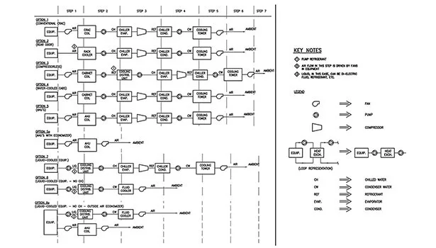
Each scenario begins at the heat source (i.e., the IT hardware) and ends with the heat being rejected to the outside ambient environment (i.e., the outdoors). Each breaks down the heat transfer path to incremental steps to include the medium (water, air, refrigerant, etc), the prime mover (fan, pump, compressor, etc), and the heat transfer component (heat exchanger, fluid-cooler, chiller, cooling tower, etc.). Then, the total system energy efficiency is estimated for each scenario. Also, for the sake of comparison, each scenario assumes the hypothetical facility employs recognized best practices such as minimized bypass air, (containment is not included in this anaylsis) balanced air and/or water distribution, and equipment properly maintained and operated per the manufacturer’s recommendations.
Figure 1 provides a schematic representation of the eight scenarios analyzed. The energy calculations are based on assumptions and/or “givens” for a representative facility of 1 MW IT equipment input and for cooling equipment selected according to current best practices to handle that total quantity of heat rejection:
1)1 megawatt (MW) of IT equipment input corresponds to approximately 285 tons of cooling.
2)For AHU systems, assume a 20?F temperature delta with 25% extra air to account for leakage, stratification, etc. (approx. 196,000 cfm total).
3)For liquid-cooled cabinet systems, assume 20?F temperature delta with no leakage (~157,000 cfm total).
4)For pumping systems with water as the medium, the specific gravity is assumed to be 1.0. For pumping systems with refrigerant as the medium, the specific gravity varies between 1.3 to 3.4, depending on which refrigerant is used.
5)For AHU systems, the fan efficiency is assumed to be 85% for 40,000 cfm fans at 0.3 in external static. For CRAH unit fans, the fan efficiency is assumed to be 70% at 16,000 cfm; the pressure drop is assumed to be 0.3 in. For cabinet fans, the fan efficiency is assumed to be 40%; the pressure drop is assumed to be 0.3 in. Cooling tower fans are assumed to be 75% efficient at 0.3 in static pressure.
6)Chilled water piping systems are assumed to be designed at 12?F delta T. Condenser water systems are assumed to be sized for 3 gpm/ton.
7)Large pumps — i.e. serving condenser or chilled water systems, are assumed to be 75% efficient. Small pumps, such as serving cooling distribution units and/or individual cabinet circuits, are assumed to be 50% efficient.
8)Typical pump heads are 75 to 125 ft for chilled water systems and 40 ft for condenser water systems. For piping between heat exchangers and/or CDU’s, assume 50 ft of head.
9)Compressors for water-cooled chillers are assumed to be selected between 0.45 and 0.55 kW/ton.
10)Air-cooled chillers and compressorized CRAC unit systems are not considered. Each has analogous systems that are considered below and have superior performance. Since the goal of this exercise is to identify which system can be more efficient, considering the systems that are clearly less efficient is not necessary.
11)Energy usage is normalized to 1 MW of input at the IT equipment
Scenario #1 – Conventional CRAHs
IT hardware chassis fans move the generated heat from the hardware chassis through the cabinet to the ambient room environment. CRAH fans pull the air across the cooling coil (heat exchanger), which absorbs the heat into a central chilled water system. The chilled water is pumped back to a chiller plant, which transfers the heat via a compressorized refrigerant cycle to either the outside environment directly (air-cooled chiller) or to a condenser-water system (water-cooled chiller). In the case of a water-cooled chiller, a pump moves the condenser water to a cooling tower (water-to-air heat exchanger), which rejects the heat to the outdoor environment. (Air-cooled chillers are not considered here.)
Scenario #2 - Rear Door-Mounted Cabinet Cooler
IT hardware chassis fans move the generated heat from the hardware chassis through a cabinet rear door-mounted cooling coil (air-to-liquid heat exchanger). Note that this scenario uses the IT hardware chassis fans to move the heat through the rear door-mounted cooler. Ideally, the air leaving the cabinet cooling coil is at ambient room conditions. The heat absorbed by the liquid in the cooling coil is pumped back to the central chiller plant where the remainder of the heat transfer methodology matches that described above in Scenario #1.
Scenario #3 - Compressorless Liquid-Cooled Cabinet
IT hardware chassis fans move the generated heat from the hardware chassis. A cabinet mounted fan moves the heated air across a cabinet-mounted cooling coil that utilizes a refrigerant (air-to-liquid heat exchanger). The refrigerant leaving the coil can be either liquid or gas. The refrigerant is then cooled by a cooling distribution unit (that can support more than a single cabinet). The refrigerant leaves the cooling distribution unit as a liquid where it is pumped back to the cabinets. The cooling distribution unit incorporates a refrigerant-to-water heat exchanger. The water is typically chilled water, which is then pumped back to a central cooling plant where it again proceeds as described in Scenario #1.
Scenario #4 - Water-Cooled Cabinet
IT hardware chassis fans move the generated heat from the hardware chassis to the air contained within a sealed cabinet. The sealed cabinet includes an integral fan-coil typically located in the bottom of the cabinet. The air within the cabinet is continuously recycled through the cabinet and the heat rejected from the IT hardware is absorbed by the integral fan-coil. Note that this scenario uses the IT hardware chassis fans to move the heat to the cabinet air and the cabinet fan-coil moves the cabinet air across the cooling coil. Ideally, there is no air leaving the cabinet to the room ambient environment. The heat absorbed by the liquid in the cabinet fan-coil is pumped back to the central chiller plant where the remainder of the heat transfer methodology matches that described in Scenario #1.
Scenario #5 - Conventional AHU’s
This scenario is essentially the same as that described in Scenario #1 except that fewer, larger AHUs replace the smaller CRAHs. The remaining three scenarios depict true water-cooled IT hardware that essentially is not commonly used in the commercial Datacom repertoire. It is quite possible that as IT equipment heat densities continue to climb, IT manufacturers may soon introduce new product lines that incorporate actual liquid mediums in direct contact with the electronics to remove the heat from within the chassis to a point outside the equipment where the “facilities utilities” can transport the heat to the outdoors.
Scenario #6 - Water-Cooled IT Hardware with Chillers
This scenario assumes introduction of IT hardware that employs a water-cooled heat sink (possibly a cold-plate), into which “utility” water is piped directly. Note that there are no chassis fans or cabinet fans and the IT hardware is liquid-cooled by standard central plant chilled water.
Scenario #7 - Liquid-Cooled Hardware with Chillers
This scenario is similar to Scenario #6 except that the IT hardware incorporates a liquid medium pump within the chassis and an associated pump to move the heat to a separate cooling distribution unit. The cooling distribution unit supports one or more liquid-cooled IT components and is essentially a liquid-to-water heat exchanger.
Chilled water from the central cooling plant cools the cooling distribution unit and the remainder of the heat transfer process again matches that described in Scenario #1.
Scenario #8 - Liquid-Cooled Hardware without Chillers
This final scenario is similar to Scenario #7 but eliminates the need for the central cooling plant and assumes the cooling distribution unit is cooled by water (or water/glycol mix), which is pumped outdoors to a fluid-cooler where fans reject the heat directly to the atmosphere.
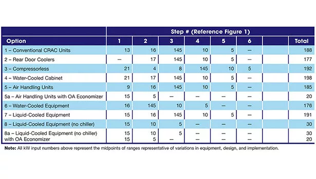
Table 1 tabulates the energy calculations for each scenario and summarizes the total energy efficiency for each. Note: All KW input numbers in the table represent the midpoints of ranges representative of variations in equipment and design.
Some general conclusions can be drawn from this analysis, as follows.
- In general, the fewer “steps” employed to move the heat from the heat generating source (IT equipment) to the outdoor atmosphere, the less energy is required and consequently the better is the overall energy efficiency. (This is not a flexible rule — just a good guideline to keep in mind when evaluating options.)
- Fewer, larger components within any particular “step” are typically more efficient than a greater quantity of smaller components providing the same function.
- The specific gravity of the liquid transport medium also plays an important role in the amount of energy consumed within each step. According to the fan equation:
Brake hp = GPM x head (in ft) x specific gravity / (6,350 x fan efficiency). It is clear that as specific gravity increases, the input power required to move the fluid increases proportionately. Water (specific gravity = 1.0) is a good transport medium. Refrigerants (specific gravity range of 1.3 to 3.4) is not as efficient a medium. Dielectric liquids (such as Fluorinert, specific gravity of 1.9) is not as good as water but is better than some refrigerants. Some specific conclusions can be drawn from this analysis, as follows:
- AHU systems are inherently more efficient than CRAC systems because of the higher efficiency of the fans.
- Compressorless liquid-cooled cabinets are somewhat inefficient due in part to the larger number of heat transfer steps, and in part to the use of a refrigerant transport medium.
- Water-cooled cabinets are less efficient than conventional CRAC unit or AHU systems, and were the least efficient of the scenarios considered.
- A rear-door cooler can be as efficient (or even slightly more efficient) compared to an AHU system.
- Liquid and water-cooled equipment (of which there are only a few commercially available) are not expected to be significantly more energy efficient than the other relatively efficient and available systems (i.e. AHU or rear-door coolers). However, due to other significant advantages, mainly that much higher load densities are achievable, these liquid and water-cooled equipment may still be found to be preferred.
- Liquid-cooled equipment without a chiller plant (also not commonly available but technically very feasible) can offer significant energy savings compared to all other options. In addition, because of the system’s simplicity, it would be expected that this type of system would be easier to maintain and significantly more reliable than the other scenarios.
kW demand in to the equipment will always balance with the energy out in the form of heat. The analysis undertaken in this article relates strictly with the energy expenditure associated with transporting that heat from the IT equipment to the ambient surrounding the facility. Obviously, some scenarios for transferring this heat are more energy efficient than others, and these need to be considered as part of the total cost of ownership of the enterprise and associated physical facility. Other issues relating to equipment reliability, maintainability, and especially the issues relating to the IT equipment configurations as they relate to the core function of the facility, must be considered completely before any decision is made in selecting the most appropriate cooling system for a data center facility.
Looking for a reprint of this article?
From high-res PDFs to custom plaques, order your copy today!


