search
Ask ACHR NEWS AI
cart
facebook twitter instagram linkedin youtube
  • Sign In
  • Subscribe
  • Sign Out
  • My Account
  • NEWS
  • TECHNOLOGY
    • Heating & Boilers
    • Cooling & Chillers
    • Pumps & Flow Controls
  • SECTORS
    • Commercial
    • Health Care
    • Data Center
    • Educational Facilities
  • DESIGN | CONSTRUCTION
  • OTHER TOPICS
    • High-Performance Buildings & Automation
    • Ventilation and IAQ
    • Commissioning
    • HVAC Retrofits
  • TODAY’S BOILER
    • Today’s Boiler Archives
    • Today’s Boiler Digital Edition
  • MORE
    • Case Studies
    • Podcasts
    • Videos
    • Directory
    • Webinars
    • ES NEWS Store
    • White Papers
  • SIGN UP
  • Back to The NEWS
Engineered Systems NEWSVentilation and IAQ

Are We Unknowingly Wrong-Sizing Ducts?

By Ernie MacFerran
Fan Duct Schematic
FIGURE 1. Simple schematic of the fan/duct assembly. Notice the manual dampers and the capped points of intake air and exhaust air.
Round Duct Properities
FIGURE 2. Graphical presentation of the 12-in. round duct properties based on the ASHRAE duct sizing chart (orange), the Ductulator (yellow) and the fan/duct assembly testing (blue).
Air Flow in louvers
FIGURE 3. Certified support data of airflow forced (pushed) through the louver compared to airflow being forced (pulled) into the louver.
Fan Duct Assembly Graphic
FIGURE 4. Graphical presentation of the fan/duct assembly operating as a supply duct (green) vs. operating as an exhaust duct (pink).
Fan Duct Schematic
Round Duct Properities
Air Flow in louvers
Fan Duct Assembly Graphic
October 31, 2012
Our team designed, built, and tested a fan/duct assembly (Figures 1 and 2), to investigate general airflow properties, only to inadvertently discover that HVAC ducts designed in the last 60 years in the U.S. have a significant design error. Now we need answers and more investigation.

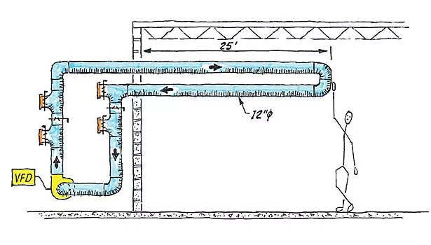
Our fan/duct assembly is schematically illustrated in Figure 3. By adjusting dampers, it can operate in three ways: as a continuously, closed, recirculating air system; as an open, positive pressure supply system discharging to atmosphere; or as an open, negative pressure exhaust system also discharging to atmosphere.

The centrifugal fan is controlled by a variable-speed controller. Airflow cfm is measured with a duct-mounted airflow monitor with a digital output display. Duct pressures are measured with an oil-filled inclined manometer.


ON TO PRESSURE LOSS

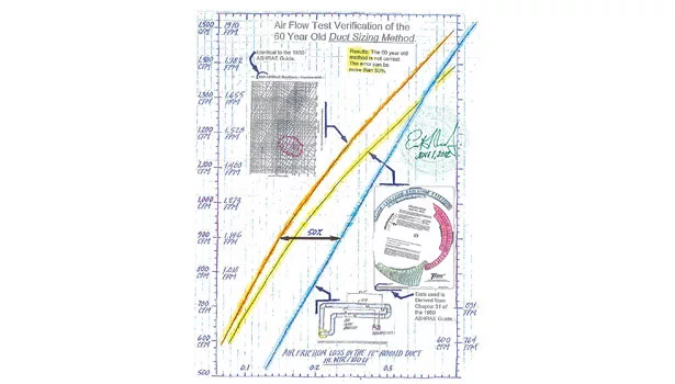
The first test was to determine the pressure loss rate (in. of water/ 100 linear ft of duct) in the straight length of duct. These test results are compared with the ASHRAE duct-sizing chart (Figure 4), highlighting the problem: as we see the data, it turns out the conventional 60-yr-old duct design criteria can be more than 50% in error.

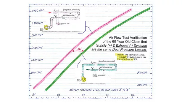
The second test was to determine whether a positive pressure duct supply system’s pressure loss (in. of water) is the same as a negative pressure duct exhaust system’s pressure loss when both are the same size duct experiencing same quantity of airflow, and when that airflow is moving in the same direction. Testing would probably be a waste of time; after all, it has always been written and preached by seasoned engineers that the pressure losses will always be the same.

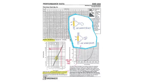
However, knowing that air is compressible and will react differently when being pushed rather than when being pulled, it didn’t seem logical that the pressure loss would be the same for both systems. One clue that supports this view is the certified airflow performance data (Figure 5) for louvers. You can see that the pressure drop differs by 20%, depending on whether the air is fan forced (pushed) or fan forced (pulled) through the louver. Interesting, but inconclusive.

With our supply duct test data and exhaust duct test data, Figure 6 compares the two sets of results. The conclusion is that there will always be a difference of 16% between the two systems with the same duct size and same airflow (flowing in the same direction).

Since 1950, the only authority of HVAC duct design has been ASHRAE. All of its universally accepted duct-sizing charts, plus the popular Ductulator, are based on airflow formulas by Daniel Bernoulli (d 1782), Henry Darcy (d 1858), Julius Weisbach (d 1871), and C.F. Colebrook (d 1939). Their formulas, expressed here:

… have been confirmed to produce the ASHRAE chart. Our team member Dorothy Schroeder, math department head at Middleton High School, confirmed this. Unfortunately, to our knowledge, there had been no hands-on airflow testing to authenticate the popular and exclusively used duct sizing method until now.


IN CONCLUSION

Based on the results of the first test, duct sizing will require starting over with laboratory airflow testing with repeatable results. The flow coefficients, Cp, based on these formulas for determining pressure loss for duct fittings (elbows, tees, etc.), also have to also be airflow tested.

These duct test results indicate the following problems:

•The operational system pressure loss is greater than the calculated losses, by up to 140%.

•The design fan motor amp draw will be less than operational.

•Fan sheaves have to be frequently changed to overcome higher pressure drops.

The benefits of correct duct sizes are that systems work correctly, they are easier to troubleshoot, testing and balancing are simpler, and good IAQ can be achieved.

Based on the results of the second test, duct sizing for both airflow being pushed and airflow being pulled through duct will require laboratory testing with repeatable results.

This shows that the exhaust fans must be located at the point of air exhaust, which results in reduced pressure drop, reduced brake horsepower, and reduced energy, Also, the pressure drop calculations will be different for supply duct and exhaust (return) duct with the same duct size, same airflow, and flowing in the same direction.

And finally, a nationally recognized air testing and balancing organization (the Associated Air Balance Council, www.aabc.com/) and others, witnessed and participated in this testing. They are considering a comprehensive airflow test to produce duct-sizing criteria to be included in their national standards handbook for the HVAC engineering design community. ES

Share This Story

Looking for a reprint of this article?
From high-res PDFs to custom plaques, order your copy today!


MacFerran is the Hillsborough County School District’s mechanical engineer responsible for the construction and maintenance of the school’s mechanical systems. He is a recipient of the Grand Award for Engineering Ex-cellence by the Florida Institute of Engineers, and was named Engineer of the Year by both the Florida West Coast ASHRAE Chapter and by the Association of Energy Engineers. He has been recognized by WHO’s WHO in America for his work in the school district, and was nominated for the district’s, “Making Miracles Happen Every Day.”

Recommended Content

JOIN TODAY
To unlock your recommendations.

Already have an account? Sign In

  • HVAC-enrollment

    The Trades Are Back: HVACR Programs See Nearly 30% Enrollment Spike

    A new wave of future technicians is entering the pipeline.  
    News
    By: Matt Jachman
  • 2025 Top 40 Under 40

    2025 Top 40 Under 40 HVACR Professionals List

    The 11th annual Top 40 Under 40 list highlights those...
    HVAC Commercial Market
    By: Hannah Belloli-Oster
  • LG Ductless Mini-Split Systems

    The 9 Types of Heat Pumps

    As the U.S. moves toward electrification, heat pumps are...
    HVAC Commercial Market
    By: Joanna R. Turpin

More Videos

Today's Boiler

Spring 2026 Issue

Today's Boiler - Spring 2026 Cover

Read More from Today's Boiler

Case in Point Logo

Smarter Hydronic Design for Data Centers - Free Webinar - January 22, 2026

Related Articles

  • ashrae-logo.jpg

    The Industry Transition To A2L Refrigerants: Where Are We and Where Are We Headed?

    See More
  • residential market

    Residential New Construction: Where Are We Now, And Where Are We Going?

    See More
  • IAQ: Florida's Teachable Moment

    See More

Related Products

See More Products
  • 0880690186-228x228.jpg

    Airflow in Ducts

See More Products

Related Directories

  • We Clean Air

    Manufacture in U.S.A. Protective "Air Canopies" that blow and clean air to form a cone of protection around people and equipment underneath, all without any filter elements that clog and need replacement.
  • Prihoda Fabric Duct

    Prihoda fabric duct diffusers are custom UL/ULC approved air diffusion devices. Lay-in laminar flow diffusers, custom graphics/colors, hold open tensioning, nozzles, antimicrobial and spot heating/cooling.
×

Sign Up. Stay Informed.

The #1 trusted source for the HVACR industry since 1926

SUBSCRIBE
  • RESOURCES
    • Advertise
    • Contact Us
    • Advisory Board
    • Classifieds
    • Submit a Letter
    • Directories
    • Store
  • ACCOUNT CENTER
    • Create an Account
    • Start a Subscription
    • Manage My Account
    • Sign Up for Newsletters
    • Visit Customer Service
    • Update Preferences
  • SERVICES
    • Marketing Services
    • Reprints
    • Market Research
    • List Rental
    • Survey/Respondent Access
  • STAY CONNECTED
    • LinkedIn
    • Facebook
    • Instagram
    • YouTube
    • X (Twitter)
  • PRIVACY
    • PRIVACY POLICY
    • TERMS & CONDITIONS
    • DO NOT SELL MY PERSONAL INFORMATION
    • PRIVACY REQUEST
    • ACCESSIBILITY

Copyright ©2026. All Rights Reserved BNP Media, Inc. and BNP Media II, LLC.

Design, CMS, Hosting & Web Development :: ePublishing