Take Control Of Your System With Differential Pressure Control
Today’s advanced control technology means that, in theory, achieving this goal is possible. In practice, however, even the most sophisticated controllers don’t always perform as promised. The result is lower levels of comfort at a higher energy expenditures.
Why? Often, the controllers are not being allowed to do their job. Indeed, the controllers can only do their job as specified if the three key conditions for hydronic control are fulfilled.
These key conditions are:
• The design flow must be available at all terminals.
• The differential pressure across control valves must not vary too much.
• Flows must be compatible at system interfaces.
The best way to attain these three conditions is to perform a balancing procedure. Balancing ensures that the plant actually performs as specified by the designer. Balancing reveals and removes a number of threats to the functionality of the installation. These can range from incorrectly implemented balancing calculations to assembly errors, such as incorrectly installed check valves or blocked filters. The balancing procedure will reveal the effects of any disturbances, identify the cause, and indicate corrective measures.
Variable flow systems are becoming more popular as pumping costs are reduced and return temperature is optimized. However, there is one disadvantage to variable flow systems: The differential pressures in the plant may vary considerably during operation.
Typical symptoms due to differential pressure variations are:
• Continuous oscillation of room temperature
• Room temperatures not reaching the required setpoints at low loads
• Maintenance problems with control valves and actuators, due to fatigue from hunting
• Higher energy costs than expected, due to unfavorable control settings to avoid instability
Sophisticated controllers cannot achieve their theoretical performance unless the conditions for their operation are correct. These conditions are governed by the design of the hydronic system. In the simplest terms, controls cannot correct for poorly designed systems. They must be designed to be as controllable as possible.
CIRCUIT CHARACTERISTIC
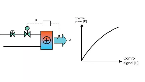
One important measure of hydronic design quality is the circuit characteristic. Figure 1 represents a typical hydronic circuit for an air heating/cooling coil. The circuit characteristic is the relationship between the control signal and the resulting thermal power from the coil and determines the controllability of the system.
The steeper the slope of the circuit characteristic curve, the higher the risk for control instability, and, as a result, control becomes more difficult. As seen in Figure 1, at a low slope, any actions from the control will result in marginal changes of thermal output, making the system quite forgiving. However, at a high slope, even tiny changes in the control signal will result in large changes of thermal output, making the system sensitive and possibly unstable.
To avoid instability problems, which effectively will ruin the control function, a low set value of the gain (corresponding to a wide P-band) is required in the controller. However, the result of a low controller gain is less control accuracy and slower response to disturbances. It is therefore crucial to avoid steep slopes of the circuit characteristic. The goal should be to achieve a linear circuit characteristic since it will minimize the slope across the entire control range.
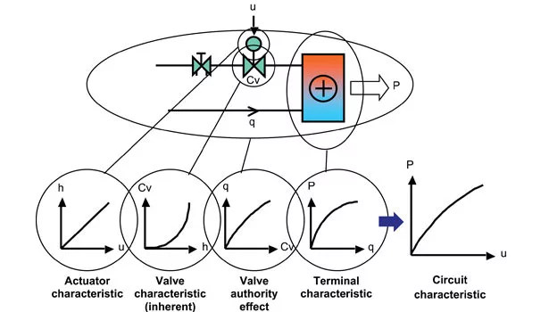
CIRCUIT CHARACTERISTIC COMPOUND
The circuit characteristics consist of:
• Actuator characteristic
• Inherent valve characteristic
• Terminal characteristic
• Valve authority
The actuator characteristic shows the relationship between the incoming control signal (u) from the controller to the actuator and the resulting valve lift (h). Usually, the characteristic is linear, but for advanced actuators, the characteristic curve may be quite nonlinear.
The inherent valve characteristic, which shows the relation between valve opening and valve capacity (Cv value), depends solely on the mechanical design of the control valve. There are different types of valve characteristics on the market; the most common ones are the linear and the equal-percentage, or actually equal-percentage modified (EQM) characteristics.
The terminal characteristic may vary a lot depending on design, size, and temperatures but is definitely nonlinear. A typical characteristic gives 50% power at 20% flow and 80% power at 50% flow. That is quite the opposite shape compared to the characteristic of an EQM valve, which counteracts the nonlinearity of the terminal.
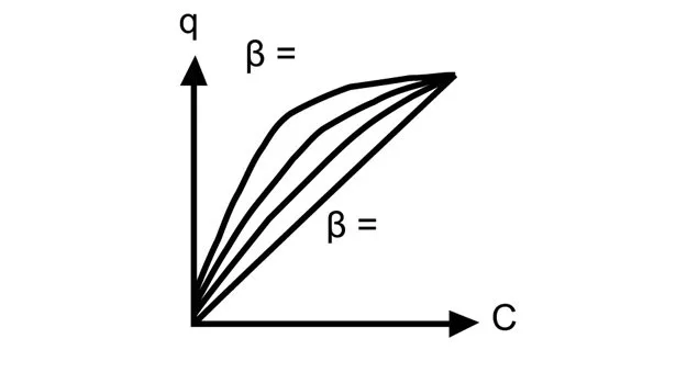
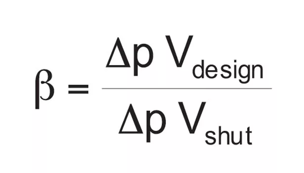
Valve authority is a measure of the change in differential pressure across a control valve during operation. The flow through a control valve depends on the differential pressure across the valve and its Cv value. The Cv value is given by the inherent valve characteristic for any valve opening. If the differential pressure is constant during operation, the relationship between Cv and water flow would be completely linear. However, in variable flow systems the differential pressure varies during operation, which means the relationship becomes more or less nonlinear. The “magnitude” of the nonlinearity is expressed by the valve authority:
b = Valve authority [-]
Dp Vdesign =
Differential pressure across fully open control valve at design flow [psi]
Dp Vshut =
Differential pressure across fully shut control valve [psi]
A high value of valve authority means that differential pressure is close to constant and the relationship between Cv value, and water flow becomes quite linear. A low value, on the other hand, means that the differential pressure will increase substantially when the valve closes, resulting in large nonlinearity between Cv value and flow. The lower the valve authority is, the more nonlinear the curve becomes.
By looking at the compound of the circuit characteristic, it is quite clear that a low valve authority will make the circuit characteristic curve unfavorable. This is why the second condition must be fulfilled; too much variation in differential pressure across a control valve leads to low authority, distorted circuit characteristics, and poor control. In addition, large variations in differential pressure will lead to interactivity between circuits, making control even more difficult.
DESIGN AND MINIMUM VALVE AUTHORITY
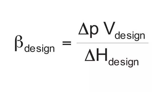
The available differential pressure across the hydronic circuit is transferred to the control valve once it shuts, which means that size, design, and control of the system determines the differential pressure across the control valve fully shut (denominator in the expression above). Hence, the circumstance of the system at any given time determines the available differential pressure across the circuits, which means that the valve authority varies during operation. If, for instance, only one control valve shuts in a system while the others are fully open, the differential pressure across that specific valve will become significantly lower than if all control valves shut at the same time. This leads to two different definitions of valve authority: design authority and minimum authority. For two-way control valves in variable flow systems, these definitions are as follows:
bdesign = Valve authority at design condition [-]
DHdesign =
Available differential pressure across circuit at design condition [psi]
Dp Vdesign =
Differential pressure across fully open control valve at design flow [psi]
bmin = Minimum valve authority [-]
DHmax =
Maximum differential pressure across circuit during operation [psi]
Both design and minimum authority definitions should be regarded when designing a system, since the level of valve authority will vary somewhere between the design authority (highest possible level) and the minimum authority (lowest possible level) during operation.
The implication of varying valve authority on the circuit characteristic during operation is shown in Figure 3. The best case represents the characteristic of the considered circuit for design authority, corresponding to a situation where all other control valves in the system are maintained fully open. The worst case, however, represents the circuit characteristic for minimum authority, corresponding effectively to a situation where all other control valves are fully shut. The latter case results in much higher differential pressure across the circuit and, thus, steeper slope of the circuit characteristic and also substantial overflow when the control valve is fully open.
HYDRONIC DESIGN
The impact of the chosen control valve on the circuit characteristic (and hence, on the controllability of the system) is quite obvious since both the valve characteristic and the valve authority depend on the control valve selection. When choosing control valves, both of these aspects must be addressed.
• The design flow must be obtained for the control valve fully open in design conditions.
• In order to facilitate control, the valve characteristic should match the terminal nonlinearity.
• To maintain a favorable circuit characteristic, the valve authority must not be too low.
In order to prevent the valve authority from distorting the circuit characteristic too much, the lowest values of design and minimum authority are:
The design authority for a control valve should not be less than 0.5, which effectively means that the design pressure drop through the fully open (two-way) control valve at design flow should at least be equal to half of the available differential pressure across the circuit at design condition. The purpose of this guideline is to make sure that the circuit characteristic at its best becomes quite close to linear, assuming the inherent characteristic of the valve is appropriately chosen.
The second condition states that the minimum authority should not fall short of 0.25, which sets the lowest level of the circuit characteristic, when it is at its worst. This condition is very important since it effectively settles the limit for the control to handle.
Besides choosing the control valves carefully, there are other design measures to implement in order to avoid low authority:
• Avoid large pipe pressure drops
• Use variable-speed pumps
• Use P stabilization valves when needed
Even if the control valve is selected with great care, there may be situations where valve authority becomes too low anyway, simply because it depends not solely on the control valve sizing but on the design of the rest of the system as well. An effective measure in this case is to install differential pressure stabilization valves. These may radically improve the prerequisites for problem-free control. ES
Looking for a reprint of this article?
From high-res PDFs to custom plaques, order your copy today!


.webp?height=200&t=1598891153&width=200 "fig1-900x550-(4).jpg")


