Design Review: Where to Locate Flow Safety Switches for Electric Heating Coils
The more we can analyze potential problems with equipment used in different types of system designs, the better we can assist our clients in design reviews
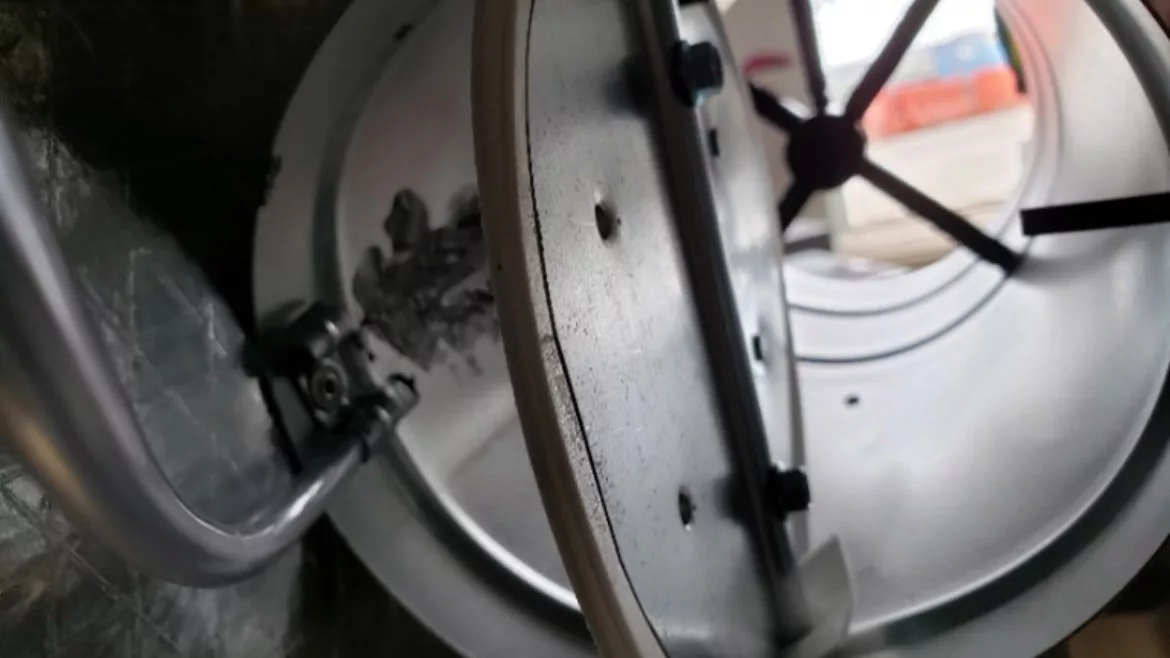
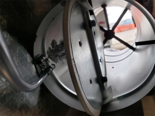
SENSOR: Flow safety switch sensor tube location. (Images courtesy of the Associated Air Balance Council)
There are many design aspects that are evaluated early in project development to help foresee potential problems that may arise during test & balance (TAB). Many of these include, but are not limited to: equipment capacities, ductwork design, project schedule, and the effectiveness of control sequences of operation. Unfortunately, there are some smaller details in specific equipment design that can make big impacts on the efficiency and effectiveness of controlling the comfort and reliability of the equipment our clients depend on. A recent project brought new light to another important factor that should be assessed during the design review: the location of a flow safety switch for electric heating coils.
The use of electric heating can have benefits over hydronic heating in certain scenarios; the initial construction costs of installing piping, pumps, boilers, and heat exchangers can add up. Not to mention the maintenance of all this equipment over time. Electric heating can surely contribute to long-term energy costs, but in Southern environments where less heating throughout the year is needed, the overall benefits of electric heating can be taken advantage of.
With electric heating, a flow safety switch is utilized to prevent the operation of the heater when airflow across the heating element is lost for any reason. This is a fail-safe to prevent potential fire hazards and/or equipment damage. We recently discovered the location of the flow switch sensing tube can have an effect on the overall performance and effectiveness of the device.
Actual field installation of equipment can cause system effects with static pressure loss, turbulence, and low-pressure areas. This should also be considered when analyzing the location of flow switch sensing tubes. Many flow safety switch devices do not engage in low-static pressure environments. In this specific application, the typical air flow safety switch would not engage until 0.05 in water column (w.c.) with a tolerance of 0.02 in w.c. It could take up to 0.07 in. w.c. static at worse case per their tolerance. On variable air volume terminal unit applications, the sensing tubes are installed on the low-pressure side of the system, after the control damper. Depending on the location of the sensing tube and the position of the control damper, the airflow switch may not engage, even when there is sufficient airflow across the heating element due to the location of the sensor tube.
In Figure 1, you can observe that the location of the sensor tube is installed in-line with the motorized damper rotating shaft. We found this setup is not ideal for large systems operating at high duct pressures. The more the control damper modulated closed, the less reliable the airflow switch was due to the location of the sensor tube. This specific project design utilized a manifold system with seven large air handling units ducted to one common plenum, serving approximately 300 variable air volume terminal units across four floors. Terminal boxes located closer to the main header experienced much higher inlet static pressure. This required the control damper to operate 15 percent to 20 percent open at normal operating conditions to maintain airflow setpoint. With the location of the sensing tube shown in Figure 1, it became obvious this would not reliably operate as intended.
Now that approximately 300 terminal boxes were installed with an unreliable heater flow switch, where do you go from there? We contacted the manufacturer and design engineer, presented them with the data and began to brainstorm. Everyone came to an agreement on a solution presented for this scenario. It was decided to “T” into the airflow measuring device (flow cross) on the terminal units and use the differential pressure to verify airflow for the pressure switch.
Overall, this turned out to be a much more reliable method than utilizing the sensing tube. The manufacturer proceeded to apply this to all the terminal boxes with problems activating the flow switches. During testing, we found that a handful of terminal boxes with low design inlet velocities would still struggle to keep the airflow switch engaged and minimum heating design airflow. This was due to the low differential pressure across the flow cross. These specific occurrences were brought to the engineer of record. The solution, where needed, was to increase the minimum airflow until the airflow switch would reliably activate to enable the heater.
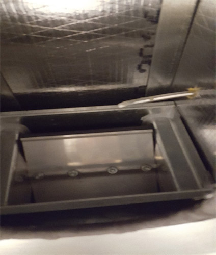
On air systems that may require terminal unit control dampers to be throttled back at certain points, electric duct heater safety switches can certainly be affected. Observe the sensor tube location in Figure 2. It would be a more effective and reliable location to verify airflow across the heating element with the damper throttled back. As you can see, the placement is directly in the airstream. Even at low damper positions, it can activate the safety switch.
Hindsight is twenty-twenty; the more we can analyze potential problems with equipment used in different types of system designs, the better we can assist our clients in design reviews. With systems utilizing more components and becoming more complicated every year, more and more smaller details should be analyzed in the design review. Aspects such as this can be addressed prior to equipment being installed in the field and provide more reliability and energy savings to the customer. Even something as simple as a duct heater flow safety switch. Not only for the safety factor, but also for the compatibility of the system it will be installed for.
Editor's note: A previous version of this story stated a typical air flow safety switch would not engage until 0.02 in water column (w.c.) with a tolerance of 0.05 in w.c. Instead, it would not engage until 0.05 in w.c. with a tolerance of 0.02 in w.c.
Looking for a reprint of this article?
From high-res PDFs to custom plaques, order your copy today!


