Measuring Air Velocity and Air Volume at Supply Grilles/Diffusers
Supply flow into an occupied space is generally a mixture of return air and fresh outdoor air that has been filtered and then conditioned through heating or cooling coils. This volume of supply air will become entrained with the room air at a known rate in order to achieve occupant comfort by providing sufficient volume flow to satisfy the number of occupants in a given space. The flow rate requirements for a room or building, and the percentage of outdoor air versus return air being delivered will vary depending on the principle purpose of the facility.It is very important to verify proper manual and automatic control of an HVAC air system. A balanced supply and exhaust will help ensure sufficient ventilation by meeting minimum air exchange rates, removing airborne contaminants which can affect air quality, and reducing operating costs. The supply flow for an area may also affect the room pressurization in relation to an adjacent room or hallway, which can cause drafts or difficulty opening and closing doors.
Capture hoods, rotating vanes, and thermal anemometers are the most common choices used to verify proper minimum flow rates; confirm proper operation of dampers, controls, and fans; and ensure the efficient use of energy.
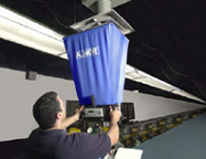
Capture hoods are popular instruments to use for measuring flow rates from supply grilles. Since they obtain measurements quickly, provide a direct air volume reading, are easy to use, and come with a variety of hood sizes to match various grilles, capture hoods are often the tool of choice (when measuring supply).
ASHRAE recommends performing a duct traverse to determine if a correction factor is needed for air capture hood measurements. Different diffuser styles, elbows attached directly to the diffuser, and dampers located just upstream of the diffuser can impair the uniformity of the flow patterns coming out of the diffuser and affect the hood reading. Be sure to choose the hood size that most closely matches the outlet size being measured. Many capture hoods on the market today include an Ak-factor function.
Utilizing these instruments effectively can help you ensure the proper balance of mechanical HVAC system supply airflows.

Nonuniform Flow Corrections
Using a capture hood on a supply opening with no diffuser or deflecting vanes may not provide accurate results due to a nonuniform air pattern and jet effects. Capture hoods are generally calibrated on a wind tunnel with a 2 x 2 ft (61 x 61 cm) hood attached to a diffuser or grille. The diffuser or grille spreads out the airflow and the capture hood will see more uniform flow. Other instruments are often used instead of capture hoods for nonuniform air flow applications.Other suitable instrument types for this application include rotating vane, thermal anemometer, velocity matrix, and swinging-vane anemometers.
Measuring air velocities at a supply opening is easily accomplished when no grille or louvers cover the opening. Divide the opening into sections of equal area and take a measurement in each section. Instruments used for this application can be a rotating vane anemometer, velocity matrix, deflecting vane anemometer, or thermo-anemometer. Add the readings and divide the sum by the total number of readings to determine the average.

A velocity matrix provides a larger measurement area, reducing the total number of samples resulting in quicker measurements. The velocity matrix can be used on a supply opening with no grille or louvers, but may not be the best choice if there are turbulent airflows. They can cause some turbulent air patterns which could affect the averaging function of the grid pressures.

Q = Ak x V
Where:
Q = flow rate in cfm (m3/h)
Ak = outlet manufacturer's correction factor
V = average velocity in fpm (m/s)
Since the introduction of the capture hood, the deflecting vane measurement has become less prevalent. It is a good option for low flow applications.

Static Pressure Measurement
Static pressure measurements are an important method of determining system operating efficiency and identifying problems such as leaky ducts, clogged filters and coils, and blocked inlets. Any of these can negatively affect occupant comfort and system operating efficiency, which can waste significant utility dollars. Unnecessary increased loads on fans and other system components can cause premature wear and untimely failure, resulting in increased maintenance costs.Static pressures in air distribution ducts can be measured using a digital micromanometer, incline manometer, or deflecting vane anemometer with static pressure probe. A digital micromanometer or incline manometer can use the standard "L-shaped" pitot probe with a hose connected from the positive port of the manometer to the static pressure leg of the pitot probe. The total pressure leg of the pitot probe and the negative port of the manometer would be open to the atmosphere.

Exhaust Grille Measurements
To adequately balance a mechanical HVAC system, it is necessary to also verify exhaust flows. Instruments such as a capture hood, rotating vane, or velocity matrix are common choices to measure exhaust flows.Capture hoods calibrated for exhaust mode can be used on return grilles without an Ak-factor. For the best accuracy, choose the hood that most closely matches the outlet size being measured and set the hood to exhaust or return mode. Also, as with supply diffusers, an alternate means of measuring flow (such as a duct traverse) is advised when determining if a correction factor needs to be applied to the hood readout.
Rotating vanes can be used on return grilles provided the vanes of the grille are straight with no deflection. Place the rotating vane approximately 1 to 2 inches (2.5 to 50 cm) away from the grille and divide the face of the grille into equal areas with the vane head taking a measurement in each location. The readings should be added and the sum divided by the total number of readings to obtain an average velocity. The average velocity can be multiplied by the free area of the grille in square feet (square meters) to obtain a cfm (m3/h) volumetric value. Rotating vanes are a good alternative if the grille is too small or too large to accommodate a capture hood.
A velocity matrix is a good choice for large return grilles with high flow rates that a capture hood cannot accommodate. The face of the return grille should be divided into sections and the velocity matrix placed in each section to obtain a reading. These readings should be added and then divided by the total number of readings to produce an average velocity. Stand-offs located on the corners of the velocity matrix aid in positioning the matrix for repeatable results by keeping the distance between the matrix and the grille consistent for each measurement.
If the exhaust outlet does not have a grille or louvers, divide the face into a grid pattern with equal areas. A larger number of measurement locations may be required to increase the accuracy of the average flow. Measurements can be taken in the center of each area using a velocity matrix or rotating vane anemometer. However, the blockage effect caused by the size of the instrument when placed in the air stream at the exhaust opening will vary from model to model, and the accuracy may be impaired.

Duct Traversing: Low to High Velocities and at High Air Temperatures
Air velocity measurements are often taken within ducts to determine flow rate. Since velocity distribution is not uniform even in the best of circumstances, a duct traverse is necessary. This involves taking a number of readings within the duct and determining average velocity.For selecting the most appropriate technique, here are some general guidelines. If air velocity in ducts normally exceeds 1,000 fpm (5 m/s), a manometer with pitot tube, thermo-anemometer, or deflecting vane anemometer with pitot probe can be used for making these measurements. However, each instrument has its limitations and may not be applicable for all jobs.
Note: The manometer is not considered to be a flow through device. This means the elevated air temperature seen by the pitot tube will not pass down through the hoses to the manometer and damage components or electronics. However, if the probe is left in the high temperature airstream for extended periods, high temperatures may eventually affect the tubing connecting the manometer to the pitot tube.
Measuring Air Velocity in Open Areas
Air velocities (and movement) in a room or space are often felt as a draft and, depending on the intensity, can be uncomfortable to most people. Cross-drafts in areas having spray booths or lab hoods can interfere with air measurement by the permanently installed air velocity monitors on the booth or hood. These and similar situations call for an air velocity measurement in the range of 50 to 200 fpm (0.25 to 1.00 m/s).Excerpted and reprinted from the Alnor HVAC Handbook from Alnor/TSI Incorporated, Shoreview, Minn. Alnor manufactures instruments for the measurement of indoor environments including air velocity, volume, pressure, and temperature. For more information, visit www.alnor.com/REDIRECTS/DIRECTORIES/ElecAds/00001/.
Publication date: 09/04/2006

Report Abusive Comment