
Transitions are needed in almost every duct run to change the size or shape of the ductwork. This article explains how to lay out rectangular transitions.
Two-Piece Transition
A duct run is often kept flat on the top to keep it against the overhead. A transition is also likely to be flat on top. If the duct is relatively small and the change is only in the height of the duct, such as a 12- x 12-inch duct changing to a 12- x 6-inch duct (Figure 1), the transition is often made in two pieces. A two-piece transition can be cut out of a sheet economically and has only two seams.

Figure 2 shows the layout for the two-piece transition shown in Figure 1. The finished fitting is 14 inches long, but the bottom piece is longer than this. This is because it must be long enough to fit the slanted side of the fitting. Use dividers or a rule to transfer dimension X from the slanted side of the pattern to the straight bottom piece pattern.
Of course, allowances for seams and connections have to be added to make a complete pattern.

Four-Piece Transition
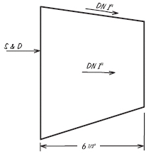
More often, transitions are made in four pieces in order to save both time and sheet metal. Figure 3 shows the plan and elevation of a typical four-piece transition. Each side of this transition is different. You must learn how to lay out these transitions and how to check your layouts by matching sides.
Always lay out the patterns for each side so that the inside is the side you see. This is so the marking instructions for forming will be on the inside of the fitting when it is finished. Also, it is less confusing if you see all the patterns from the same side. To lay out the patterns with the inside up, picture yourself as being inside the fitting and looking at the side. You can then visualize whether an edge slants to the left or to the right.
The length of the finished fitting in Figure 3 is 6-1/2 inches, but none of the patterns will be 6-1/2 inches long. Because each side slants, the length of each pattern piece will be determined by the true length of the centerline of that side.
Figure 4 shows a plan view of the fitting marked to explain the layout. Each side is identified by a number. The corners are identified with letters.

Lay Out Side 1
To lay out side 1:

To complete the pattern, add allowances for seams and connectors. Mark the pattern as shown to help you keep everything straight in your head. Mark the following:
In actual shop work, you usually won't have a plan view to work from. And once you learn the method, you won't need the letters. They are only part of the learning process. What you will generally have is a shop ticket or a sketch to work from like the one in Figure 6. As you gain experience, this is all you will need. If you have trouble visualizing the fitting, make a freehand sketch of the plan view and letter the corners.
Lay Out Side 2
Lay out side 2 (Figure 5B) as you laid out side 1:
9 - (6 + 1) = 2 inches
The third side of the triangle is the true length of MN (by measurement, 6-3/4 inches) (Figure 5B).
11 - (7 + 1) = 3 inches
Add allowances for seams and connections. Mark the pattern. Add XXX near edge BF and XXXX near edge AE.
Lay Out Sides 3 And 4
The patterns for sides 3 (Figure 5C) and 4 (Figure 5D) are laid out in the same way. Add the X marks as shown.Check The Patterns
You won't have the corner letters on your pattern (they are just for explanation), so use the X marks on the edges to check the patterns and make sure the mating edges will fit together:
The X marks can also be used to avoid confusion when the fitting is assembled. The two edges with XXXX must be assembled together, the two edges with XXX must be assembled together, and so on.
Excerpted and reprinted from Layout for Duct Fittings by Leo A. Meyer, one of the books in the Indoor Environment Technician's Library series published by LAMA Books. For over 30 years, Meyer has been writing and publishing training materials for the HVAC industry. His books cover a wide range of topics, including heating and cooling, indoor air quality, sheet metal work, electricity basics, safety, and others. For more information, visit www.lamabooks.com.
Publication date: 09/05/2005

Report Abusive Comment