Should I Have a Thermal Camera in My Tool Bag?
Case studies reveal the multiple uses of thermal imaging

FIGURE 1 - UNCOMFORTABLE CUBICLES: A 40-plus-story office building was plagued with high energy consumption, poor space comfort, and low productivity.
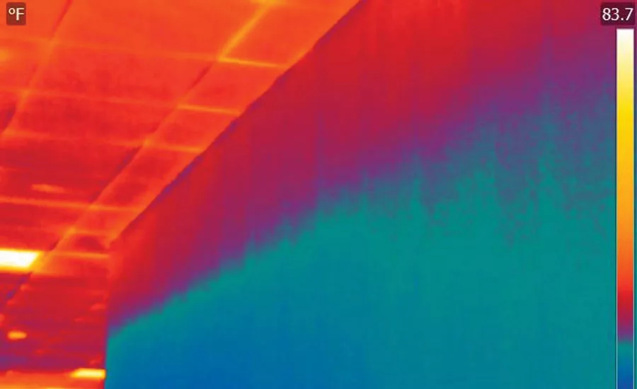
FIGURE 2 - THE THERMAL IMAGE: A look at the problem area through a thermal imager revealed that adding additional heat to the variable air volume (VAV) boxes did add more heating capacity to the space, but, in turn, increased the stratification of the space.
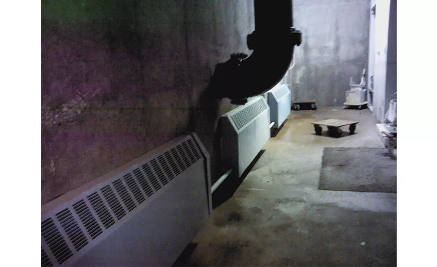
FIGURE 3 - LOCATING A LEAK: Following a renovation in the 1990s, a boiler servicing this water treatment plant was failing every couple of years.
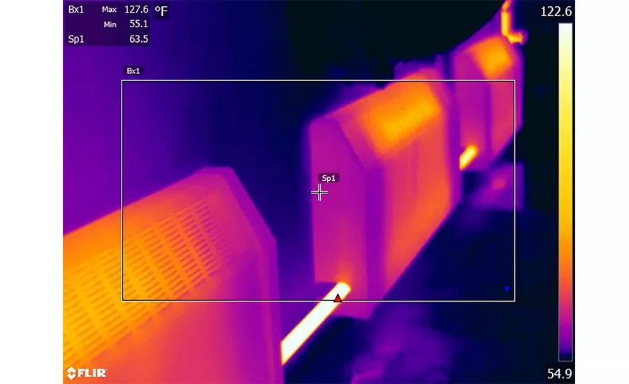
FIGURE 4 - MISSING INSULATION: A FLIR T620 camera showed that the piping serving the lower level of the building was lacking insulation.
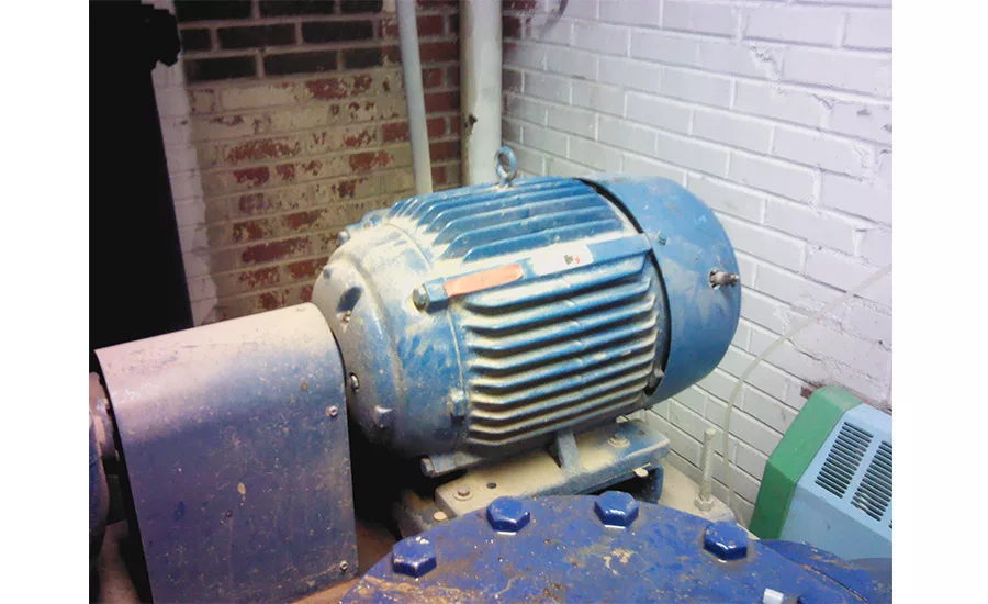
FIGURE 5 - NOISY PUMP: During commissioning activities, a newly installed pump was making an unusual noise.
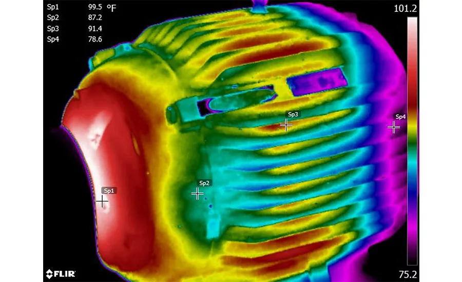
FIGURE 6 - BAD BEARING: A thermal imaging scan indicated a failing bearing in the new pumps.
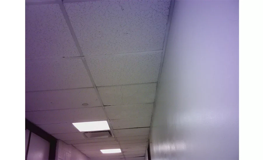
FIGURE 7 - UNKNOWN HEAT SOURCE: A heat anomaly could be felt in a hallway.
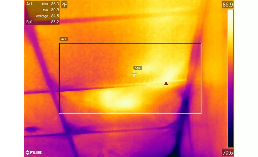
FIGURE 8 - LACK OF INSULATION: Thermal imaging indicated that newly installed hot water piping had never been insulated. The heat from the piping was radiating to the tile below and subsequently heating the room.
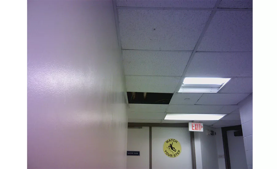
FIGURE 9 - HALLWAY HEAT: Another look at the uninsulated hallway pipes.

FIGURE 10 - OUT OF SIGHT, OUT OF MIND: Without a thermal imager, one may never have detected this missing pipe insulation.

FIGURE 11 - HIGH VOLTAGE: A hot wire within a storage closet adjacent to the registration desk at a major hotel could have led to a major fire catastrophe.
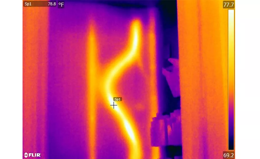
FIGURE 12 - PROBLEM SOLVED: Luckily, using a thermal camera, this hot wire was located and fixed, resolving a very dangerous situation.

FIGURE 13 - TOO HOT, TOO COLD: Guests at this 200-plus room hotel commonly complained of lukewarm or scalding water temperatures.
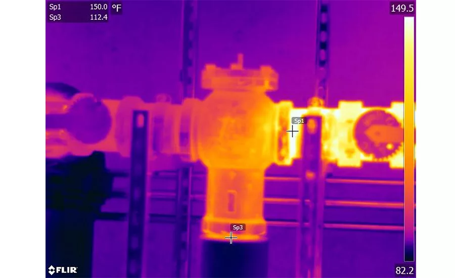
FIGURE 14 - JUST RIGHT: Using thermal imaging technology, it was determined that the mixed water temperature leaving the thermostatic mixing valve was varying considerably. The threads of the piping connection of the valve have a high emissivity and were determined to be accurate by comparing the temperatures of the entering water temperature with the thermal images. The defective valve was replaced.

FIGURE 15 - ON THE SPOT: An infrared thermometer (spot pyrometer) is one pixel of temperature measurement. A 640-by-480-pixel thermal camera has 307,200 pixels. Each pixel averages the temperatures within it.
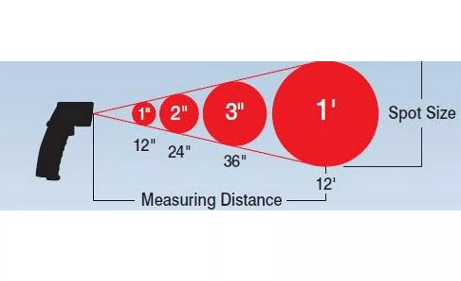
FIGURE 16 - SPOT RATIO: At a distance of 12 feet, the typical infrared thermometer (distance to spot ratio 12:1) will average temperatures within a radius of 1 foot. The typical 640-by-480-pixel thermal camera can measure a 1-foot radius at approximately 330 feet — much better.
As I’ve moved through my career in this business, whether it be as a service technician, building automation technician, energy auditor, or a commissioning agent, I look back and wonder how I performed my job without a thermal imaging camera in my tool bag. Considering everything we do revolves around heat transfer, there’s no better way to visualize heat transfer than with thermal imaging.
When a thermal camera is brought into a situation, it’s often a last resort when all of our trial and error didn’t work. Considering how expensive some cameras are, most of us can relate. I’m not going to spend time comparing types of cameras, though I will say the technology is getting more affordable every day, and the quick return on investment makes this technology a no-brainer.
The intent of this article is to share a few case studies to demonstrate how a thermal-imaging camera can be used in energy audits, commissioning, etc. In many cases, trial and error to fix a customer complaint only made the problem worse.
Case One: High-rise Cold Complaints
Building Type: 40-plus floors Office Building
HVAC System: Air handler serving variable air volume (VAV) boxes with electric reheat.
Complaint: The lower floors of the building are very cold and drafty.
Type: Comfort, energy, and productivity.
Looking for quick answers on air conditioning, heating and refrigeration topics? Try Ask ACHR NEWS, our new smart AI search tool. Ask ACHR NEWS
Effects: High energy consumption, poor space comfort, and low productivity.
Cause: The initial response was typical. Why are the VAV boxes not working? As it turns out, the boxes were working properly. In an effort to provide more heat in the space, additional heat was added to the VAV boxes. The space was still cold. Alternately, there was a request to add additional heat to the space.
I explored the space with thermal imaging (see Figures 1 and 2). I found that adding additional heat to the VAV boxes did add more heating capacity to the space, but, in turn, increased the stratification of the space.
Where is the cold being introduced into the space?
Next was to look at the envelope. This revealed infiltration of very cold air (approximately 17°F) into the space through the envelope. You can assume frost is forming in the walls.
The stratification is a result of major infiltration of very cold air. The infiltration was a result of the space being negatively pressurized relative to the outside. But, what is the air-balance ratio between return and supply air? The air-balance report showed a slight positive pressure (trust, but verify). The major problem is on the lowest floor. The air handler serves several floors, including this one.
As it turns out, the negative pressure in the lower floor was being caused by the stack effect taking place in the elevator shaft. This, in turn, was caused by a failed elevator shaft pressurization fan and poorly performing gaskets on the elevator doors.
Solutions: Repair the elevator shaft pressurization fan. Replace and adjust the elevator door gasket material.
Case Two: Why is My Boiler Continually Failing?
Building Type: A water treatment plant.
HVAC System: Hot water radiant heating serving three zones.
Complaint: Why is my boiler failing every few years?
Type: Comfort, energy, and equipment life.
Effects: Poor boiler performance, short equipment service life, and poor space conditions.
Cause: Radiant heating is used throughout the water treatment facility to prevent high humidity and condensation collection on surfaces. The plant was renovated in the 90s. Ever since the renovation, the boiler serving the heating system was replaced every few years due to cracks and leaking.
They were originally running the water temperature in the plant at 160°-180°. Now, they run the boiler from 180°-200° and can never get the space where they want it. During the renovation, the envelope of the building was sealed and insulation was added. Space pressure is at slight positive, just where it should be.
After walking the plant with my FLIR T620 camera, the solution revealed itself (see Figures 3 and 4). The boiler was suppling 180° water. Three circulation pumps were used for the radiant heat zones. Zone 1, serving the ground level, was returning water at a temperature of approximately 160°. Zone 2, serving the ground level, was returning a water temperature of 155°. Zone 3 — the largest zone, serving the lower level — was returning a water temperature of 138°. We already know the cold return water is the problem with the boiler, but, why?
Thermal imaging indicates that none of the piping serving the lower level has insulation. The total length of this piping loop is approximately 500 feet. Since all of the piping runs parallel and in contact to underground concrete walls, a great deal of heat is lost to the walls and not the space.
Solutions: The insulation was replaced and the boiler runtime was greatly reduced, the return water temperatures were back above 140°, and the space was much more comfortable with reduced humidity. A cost-benefit analysis was performed, and the savings were quite impressive with a very short payback (another subject entirely).
Case Three: Noise in Mechanical Room
Building Type: A water treatment plant.
Equipment type: A base mount pump.
Complaint: In this case, there was no complaint from the customer. In fact, they didn’t recognize there was a problem. While commissioning activities were being conducted elsewhere in the plant on a different system, it became evident to me that the newly installed pump didn’t sound right. Although the noise was barely noticeable, it was unusual. It’s good to get in the habit of turning your camera on as soon as you enter the building. I wouldn’t advise looking through the camera while walking around the building, but I would advise taking the short time to take a large perspective of the building. You may just notice something that’s out of your scope but could save the client time and money. In this case, a thermal imager indicated a failing bearing in the new pumps (see Figures 5 and 6).
Case Four: Missing Piping Insulation
Building Type: 200-plus-room hotel in Pittsburgh
Equipment Type: Hot water heat.
Complaint: No complaint was made. There was a comment after this discovery that the hallway was always hot, year-round.
Type: Energy and comfort.
Effects: Overheating of adjacent space.
Cause: This is another instance where an energy audit and building assessment was being performed, and having a thermal imaging camera available during a walk-through paid dividends. I noticed a heat anomaly in a hallway. Upon further investigation, thermal imaging indicated the five-year-old hot water piping had never been insulated (see Figures 7, 8, 9, and 10). The heat from the piping was radiating to the tile below and subsequently heating the room.
Solutions: Piping insulation was replaced and room comfort returned.
Case Five: Inadequate Wire Size for New Heater
Building Type: A 200-plus-room hotel in Boston.
Equipment Type: A forced-air electric heater.
Complaint: No complaint was made.
Type: Life safety.
Effects: No obvious effects.
Cause: This is yet another instance where an energy audit revealed a major issue during a walk-through with a thermal camera (see Figures 11 and 12). Within the last month, a new heater was installed in an area used by the valet staff. I was walking the building, looking at various things, when this hot wire came into view. Had this issue not been found and immediately addressed, a loss from fire was imminent.
Solutions: The circuit was repaired.
Case Six: Thermostatic Mixing Valve
Building Type: A 200-plus-room hotel in Boston
Complaint: Guests often complained of either very hot or lukewarm hot water, creating a lack of comfort and a scald risk.
Type: Guest comfort and life safety.
Cause: There is one thermostatic mixing valve serving the domestic hot water to the guest rooms. The purpose of this valve is to take the 150° hot water made by a boiler and mix it with cold water to supply 120° water for guests. The operation of this thermostatic mixing valve is in question. Since there are no thermometers installed in the piping, it is difficult to tell if it’s working. The only temperature sensor available is the hot water temperature entering the valve. The owner placed a data logger on the piping to monitor and trend the water temperatures. The data recovered from the logger indicated it varied in temperature slightly. The thermistors attached to the mixing valve did not react quickly enough to catch the rapidly changing water temperature. Using thermal imaging technology (see Figures 13 and 14), we were able to determine the mixed water temperature leaving the valve was varying considerably. The threads of the piping connection of the valve have a high emissivity and were determined to be accurate by comparing the temperatures of the entering water temperature with the thermal images.
Solutions: The valve was determined to be defective and was replaced.
THERMAL NECESSITY
During a recent conversation with a group of HVAC service technicians, one of them asked, “Why do I need a thermal camera, I have an infrared thermometer?”
Without going into great detail about resolution and spot-size ratio, I’ll leave you with a simple explanation (see Figures 15 and 16): An infrared thermometer (spot pyrometer) is one pixel of temperature measurement. A 640-by-480-pixel thermal camera has 307,200 pixels. Each pixel averages the temperatures within it. So, at a distance of 12 feet, the typical infrared thermometer (distance to spot ratio 12:1) will average temperatures within a radius of 1 foot. The before mentioned typical 640-by-480-pixel camera can measure a 1-foot radius at approximately 330 feet. Whoa, much better.
In summary, the days of thermal imaging being a last resort are, and should be, over. We work and live in a world with energy moving to and from everything. Now, more than ever, thermal imaging technology should be one of the first tools you buy.
Publication date: 2/15/2016
Want more HVAC industry news and information? Join The NEWS on Facebook, Twitter, and LinkedIn today!
Looking for a reprint of this article?
From high-res PDFs to custom plaques, order your copy today!


