Identifying the most common problems encountered in fans and air-handling systems is often treated like an art instead of a science; it takes knowledge, inquisitiveness, common sense, mechanical aptitude, and experience to diagnose the cause of some very subtle problems.
Technology provides many tools for accurate and reliable fan and system design. Gone are the days when cheap energy allowed the use of rules of thumb and large safety factors to be part of the design process. However, even with modern technology, instances occur when the actual application does not perform as expected.
That’s when we need to apply troubleshooting. It is the effort to identify and resolve differences between what was expected and what actually happened.
This article is a guide for identifying the most common problems encountered in fans and air-handling systems. This is often treated like an art instead of a science because many problems are subtle and hard to diagnose. It takes a lot of knowledge, inquisitiveness, common sense, mechanical aptitude, and years of experience to diagnose the cause of some very subtle problems.
A professional consultant or troubleshooter may ultimately be required to identify and solve the worst problems. The intent of this article is to point you in the right direction.
SAFETY FIRST
Fans and air-handling systems come in many sizes, shapes, and complexities. It is critical to realize the limitations of any investigation, to ensure the safety of all personnel and the safe operation of installed equipment.Operating a piece of equipment or system when there are obvious mechanical, electrical, or aerodynamic instabilities requires extremely good judgment. Investigations should only be conducted by qualified personnel. Catastrophic failures can result in death or serious physical damage when rotating equipment is involved.
Physical inspections should be made only when the fan and system are shut down and locked out both electrically and mechanically, so that windmilling cannot occur.
Recommended reading for troubleshooting includes Air Movement and Control Association (AMCA) publications 202 Troubleshooting, and 410 Recommended Safety Practices for Users and Installers of Industrial and Commercial Fans prior to any investigation. In addition, refer to manufacturers’ installation and maintenance literature, and review OSHA requirements for guarding.
Proper attire includes safety shoes, a hard hat, and safety glasses. Improper attire includes ties or loose-fitting clothing. Safety harnesses and other gear must be worn as needed. In no case should the troubleshooter become part of the problem due to a lapse in safety.
REQUIRED INFO
Equipment identification:It is vitally important that the equipment in question be properly identified along with other related information. This allows the equipment manufacturer’s records to be accessed, allowing a starting point for an initial evaluation of the equipment at the time it left the factory. The following information is necessary:• Customer name.
• User.
• Jobsite location.
• Fan serial number or order number.
• Fan model.
• Specific fan designation if several fans are involved.
Detailed description of the problem:It is essential for those involved to properly describe the problem in as detailed and clear a manner as possible. Information is often transferred through several different people; however, word of mouth is normally not accurate enough.
Complete descriptions, including noises, are encouraged. They can be very helpful in identifying a problem. As many details as possible should be included. For example, if a system is low in airflow, related rating parameters (such as pressure, power, speed, elevation, and temperature) should also be provided. A statement of the actual airflow, compared to the desired airflow, should be included. Test measurements and their locations are very useful; the measurements themselves are often a clue to the problem.
Initial fan and system inspection:Most problems occur during the startup phase of any installation. Many simpler problems can be solved up front by conducting a thorough inspection. This is normally the user’s responsibility prior to getting others involved. The following checklist from AMCA 202 contains the items to be inspected:
• All fan parts and accessories should be installed, aligned, and operational.
• Check all tie-down bolts so that the fan is firmly held in place on its foundation.
• Check all ductwork connections so that flexible material doesn’t suck in, leak, or become short circuited by having the fan support ductwork or other parts of the system.
• Make sure all driveline components (bearings, couplings, v-belts, motors, etc.) are aligned and properly tensioned. Make sure all v-belts are matched and the bearings have been tightened to the base and to the shaft. Make sure bearings are lubricated with the proper type and amount of grease.
• Make sure the fan wheel is properly aligned with the inlet bell and housing, that it’s free to turn, and that when momentarily energized, it will turn in the right direction.
• Check the fan and system for any obstructions, build-up, leaks, missing parts, etc.
• Run the fan at full speed. Verify that the fan is running close to the design speed, that it’s running smoothly, and that the bearings are not running hot. Take a power measurement to make sure the fan is not overloading the motor.
• Let the fan run 24 hours. Recheck all of the items listed once again, particularly the v-belt tension.
The results of this initial inspection should be kept on record for future reference. If a problem does occur later on, it will serve as a beginning point of any evaluation.
Contact person:If there is a problem, you need to designate a contact person who will have continuing, intimate knowledge of fan and system status; someone who knows the problem and what has already been tried to solve it. This person is the contact person and liaison for others who may be required to visit the jobsite. This person’s name, title, address, and phone numbers should be readily available. Keep this person abreast of all actions that may be contemplated.
Problem prioritization:There must be some determination as to the seriousness and timeliness of the problem resolution. Many misunderstandings occur when a priority has not been established. Everyone involved in the resolution needs to recognize that a problem exists and that a reasonable plan of action and solution is usually in the best interest of everyone.
PROBLEM CATEGORIES
Now it’s time to identify the nature or category of the specific problem. The following four categories narrow the focus and speed up the evaluation process.1. Aerodynamic performance:This applies to any of the five rating parameters of flow, pressure, speed, power, and density, and how they compare to their respective design quantities.
2. Noise:This applies to any problem in which the ears are the main sensors. Noise and vibration are similar in that they both have amplitude and frequency, but noise is a much lower amplitude and energy content and is measured in dB referenced to Watts. Generally speaking, noise has a much wider frequency range and a higher upper limit than vibration (63 Hz to 10 KHz).
3. Vibration:This applies to any problem in which the hands or touching are the main sensor. Amplitude is large when there is a problem. It has a much greater energy content with a smaller frequency range (3 Hz to perhaps 500 Hz).
4. Premature failure:This applies to anything that does not meet lifetime expectations. Failure does not necessarily mean a catastrophic failure; it doesn’t have to blow up; but it is a dramatic shortening of the length of time that would have been considered the useful life of the component.
SUMMARY
Satisfactory applications occur when all aspects of the installation are in harmony with each other. Proper operation, constant monitoring, and maintenance are also part of the equation. Troubleshooting must be employed when one of these areas becomes a problem.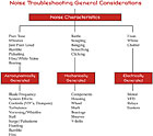
Sidebar: Noise Troubleshooting
Noise is generally described as low-quality, unwanted sound. Our ears sense noise; vibration is sensed by feel or touch. Sources of noise can usually be identified by some form of characteristic sound to which we can relate. Words such as tone, rattle, pitch, steady or unsteady, and intermittent can help define whether the source of the noise is aerodynamic, mechanical, or electrical.Aerodynamically generated noise is characterized by a continuous broadband frequency spectrum with a superimposed tone. The tone is typically objectionable when it becomes 4-6 dB louder than the rest of the spectrum. The tone can be the blade frequency, which is a function of the fan type. It can become very objectionable when system effects and various controls cause it to rise higher than normal. Additional causes include turbulence, high velocities, and instabilities due to pulsation and surge.
Mechanically generated noise has a different sound quality and characteristic. This metallic sound is caused by metal-to-metal contact. This contact may be constant or intermittent.
Electrically generated noise is a function of motors, relays, controls, or unbalanced line voltages into the motor. Sometimes an improperly matched drive and motor can cause a substantial increase in motor noise due to imperfect sine wave simulation.
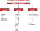
Sidebar: Vibration Troubleshooting
There are many different sources of vibration. One of the most difficult tasks in troubleshooting fans and systems is the systematic identification of vibration characteristics (amplitude, frequency, location, direction, units of measurement) as a function of operating point location on the fan curve and control settings. Identifying the source can be extremely difficult.Vibration in housings and ductwork is most often aerodynamically generated. This is a forced vibration in which the energy and characteristics of the airstream are large enough to cause sympathetic vibration in the housing and ductwork. Turbulence, pulsation, and the blade frequency tone are examples of forced vibration due to aerodynamics.
Vibration can also be the result of a resonance. This occurs when the natural frequency of a duct or housing panel coincides with a specific aerodynamic excitation such as rotating stall, vortex shedding, or the blade frequency if it is strong enough.
Mechanically generated vibrations occur from unbalance, resonance, looseness, and rubbing. Electrically generated vibrations result from torsional fluctuations, eddy current-induced fields, and improper wiring.

Sidebar: Failures
It’s obvious that when a component physically fails and flies apart upon startup, it’s a premature failure. However, premature failures also occur when fans and components do not satisfy their expected life. This is hard to quantify because very few records are kept and once a fan is installed, it is easily forgotten.The best prevention against premature failure is a good, conscientious preventative maintenance program that includes inspections and the recording of vibration levels. Repairs should take place at the first sign of a problem, not after damage has occurred to other parts.
In general, equipment life should be consistent with the application. For example, HVAC equipment may be expected to last 10 years, industrial equipment about 15 years, and power plant equipment about 30 years. This means that the equipment itself, with proper maintenance, should still be around after these time frames.
This article was contributed by Greenheck Fan Corp. For more information, contact Jay Bauman, sales and marketing manager, Fans and Ventilators, at 715-355-2256; jay.bauman@greenheck.com.
Publication date:09/29/2008

Report Abusive Comment