Addressing Leaks in CO₂ Refrigeration Systems
HVAC contractors that carefully follow the proper sequence of operations can minimize the threat of CO₂ leakage for their customers, themselves, and the environment
Refrigerant leaks are an ongoing concern for commercial refrigeration facility managers and HVAC contractors alike.
According to the U.S. Environmental Protection Agency’s (EPA’s) GreenChill program, the typical supermarket has an annual leak rate of about 25%, and the average store contains about 3,500 pounds of refrigerant.
An impending hydrofluorocarbon (HFC) phasedown may only compound the issue of refrigerant leaks as supermarket operators tear down existing refrigeration systems and implement new equipment designed to operate using lower global warming potential (GWP) refrigerants.
Through this transition, one primary alternative refrigerant that’s often considered is CO₂ refrigeration, more commonly identified as R-744. CO₂ is attractive because for many reasons, including its environmental impact, high energy efficiency, and wide working temperature range. And, perhaps most importantly, it boasts a miniscule GWP of 1.
Under Pressure
While R-744’s low GWP number is highly attractive to those working in and out of the industry, the gas is not without its share of challenges. Perhaps the most notable con is the high pressure requirements necessary to operate CO₂ systems.
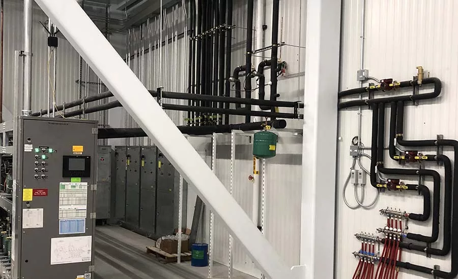
According to Andre Patenaude, director of solutions strategy, Copeland, as medium-temperature (MT) compressors discharge into a gas cooler on the roof, pressures could reach 1,400 psi on a 95°F summer day. MT discharge lines are constructed with stainless steel or special ferrous alloy copper to handle these pressures. Within a facility and/or machine room, a high-pressure expansion valve reduces the refrigerant pressure exiting the gas cooler to around 550 psi and transfers it to a receiver tank, commonly referred to as a flash tank. Liquid refrigerant exits at the bottom of the flash tank via a main liquid line at 40° (550 psi) and feeds all the MT evaporators, which operate at about 22° (420 psi). It also feeds all the low-temperature (LT) evaporators, which operate near minus 20°, at an even lower pressure of 200 psi.
While such high pressures often create anxiousness for service technicians when they first encounter CO₂ transcritical booster systems, understanding how and why those pressures occur can provide them a greater comfort level.
Looking for quick answers on air conditioning, heating and refrigeration topics? Try Ask ACHR NEWS, our new smart AI search tool. Ask ACHR NEWS
“From a pressure standpoint, we had some reservations,” said Adam Dykstra, refrigeration operations manager, DeTroye Electric Service, Oostburg, Wisconsin. “Going from 20 pounds of suction to a system that runs at 300 pounds of suction, and high head pressure of 400 to 1,800, was concerning.”
While CO₂ refrigerant may not be as deadly to the environment as its HFC peers, there are other concerns that exist when it escapes a system, i.e., it accumulates at the ground level; it may displaces the air; and it’s odorless and, thus, cannot be detected by smell.
The Occupational Safety and Health Administration stipulates CO₂ exposure at 5,000 ppm for occupational exposure limit (OEL). At 40,000 ppm, CO₂ leakage is considered immediately dangerous to life or health (IDLH).
When it comes to addressing R-744 system leaks, time and experience have been DeTroye’s guiding forces.
“On the first rack we completed, we noticed leaks forming on the low-temperature side because the dissimilar metals were expanding at different rates,” said Dykstra. “We’ve learned how to better navigate that with each subsequent project.”
If there is oil in the system, we learned that pressure leaks may occur after the oil, so it’s important to check the pressure relief hoses to ensure they’re intact,” continued Dykstra. “We’ve also started implementing Tattles on the pressure relief manifold, which helps us identify the exact spot where a leak is occurring. Finally, we always make sure our connections are tight, including items such as suction transducers, because, over time, those items may start to leak.”
Identifying R-744 leaks requires significant attention to detail.
“Given the pressures in CO₂ systems, I initially thought you would be able to see these leaks from outer space or, at the very least, hear them,” said Mark Doninelli, vice president, Estes Refrigeration. “However, that's really not the case. Oftentimes, leaks on threaded fittings are extremely slow. They’re seemingly escaping one molecule at a time. I'm not kidding.”
CO₂ refrigeration systems are extremely sophisticated, and Doninelli insists techs study up on all aspects of a system and learn the proper sequence of operation before getting to work.
“With many HFC systems, you can separate the pressure sides with a thermostatic expansion valve, but CO₂ systems use electronic expansion valves and flash tanks, which are a bit more complicated,” he said. “When dealing with pressure and leaks, it’s important to note that the CO₂ must be kept cool. These are not your standard refrigerant diagrams. There’s a lot more going on, and techs must be aware of this.”
One easy yet crucial step that Doninelli recommends in CO₂ refrigeration systems: doping and tape.
“Your threaded fittings need to be both doped and taped with Teflon,” he said. “If you use one without the other, your system is likely going to leak. Take my word for it.”
While leaks will always be a concern in high-pressure refrigeration systems, contractors that carefully learn these systems and follow the proper sequence of operations can minimize the threat for their customers, themselves, and the environment.
Looking for a reprint of this article?
From high-res PDFs to custom plaques, order your copy today!


