

The use of CO2 as a refrigerant (R-744) in commercial refrigeration is expected to rise significantly in the U.S. over the next several years. With a global warming potential (GWP) of 1 and zero ozone depletion potential (ODP), CO2 enables food retailers to meet their sustainability goals and comply with environmental regulations.
Although CO2 refrigeration has been used globally for decades, U.S. supermarket owners, operators and service technicians have had very little (if any) exposure to it. The characteristics of CO2 refrigeration are quite different from traditional hydrofluorocarbon (HFC)-based systems, which has created some misconceptions about applying it within U.S. food retail outlets.
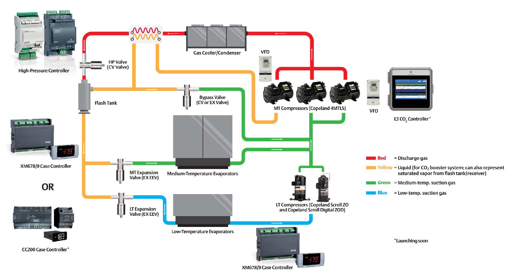
CO2 transcritical booster systems are designed so that medium-temperature (MT) compressors discharge into a gas cooler, typically located on the roof of a facility. On a hot summer day, system pressures could potentially reach 1,400 psig, requiring refrigerant to first be cooled before it can be condensed. Refrigerant is circulated back into the building through a stainless-steel line and a high-pressure valve (HPV), which drops the pressure to a useable state (550 psig) and deposits a refrigerant mixture of vapor and liquid inside the flash tank at 40 °F equivalent saturation.
Click chart to enlarge
Next, the system circulates the 40 °F liquid through insulated liquid lines to feed all the MT and low-temperature (LT) cases and provide the cooling loads. The MT cases are equipped with electronic expansion valves (EEVs), and the MT suction gas feeds the MT compressors. On the LT side, where loads could be -20 °F, the cases are fitted with an EEV and supported by a separate set of LT compressors that discharge into the MT suction group.
The system also utilizes a bypass line that’s designed to relieve the pressure on the flash tank. As ambient temperatures rise and fall, flash tank pressures can fluctuate. Thus, the bypass line helps to release the excess flash tank pressure through a bypass gas valve and stabilize it to approximately 550 psig (pressure may vary based on system design), where it is directed into the MT suction group. In effect, the MT compressors are being fed by three sources:
- The total heat of rejection from the LT compressors
- The MT suction from the evaporators
- The excess flash gas via the bypass line
The system is called a booster system because the LT compressors are not discharging directly to the gas cooler, as in a typical HFC system. Instead, they discharge into the MT compressors, thereby allowing the MT compressors to boost the refrigerant to the gas cooler.

Report Abusive Comment