

Compared to systems based on legacy hydrofluorocarbon (HFC) refrigerants, CO2 transcritical booster (TCB) systems have unique characteristics, high-pressure management strategies and design considerations.
Click graphic to enlarge
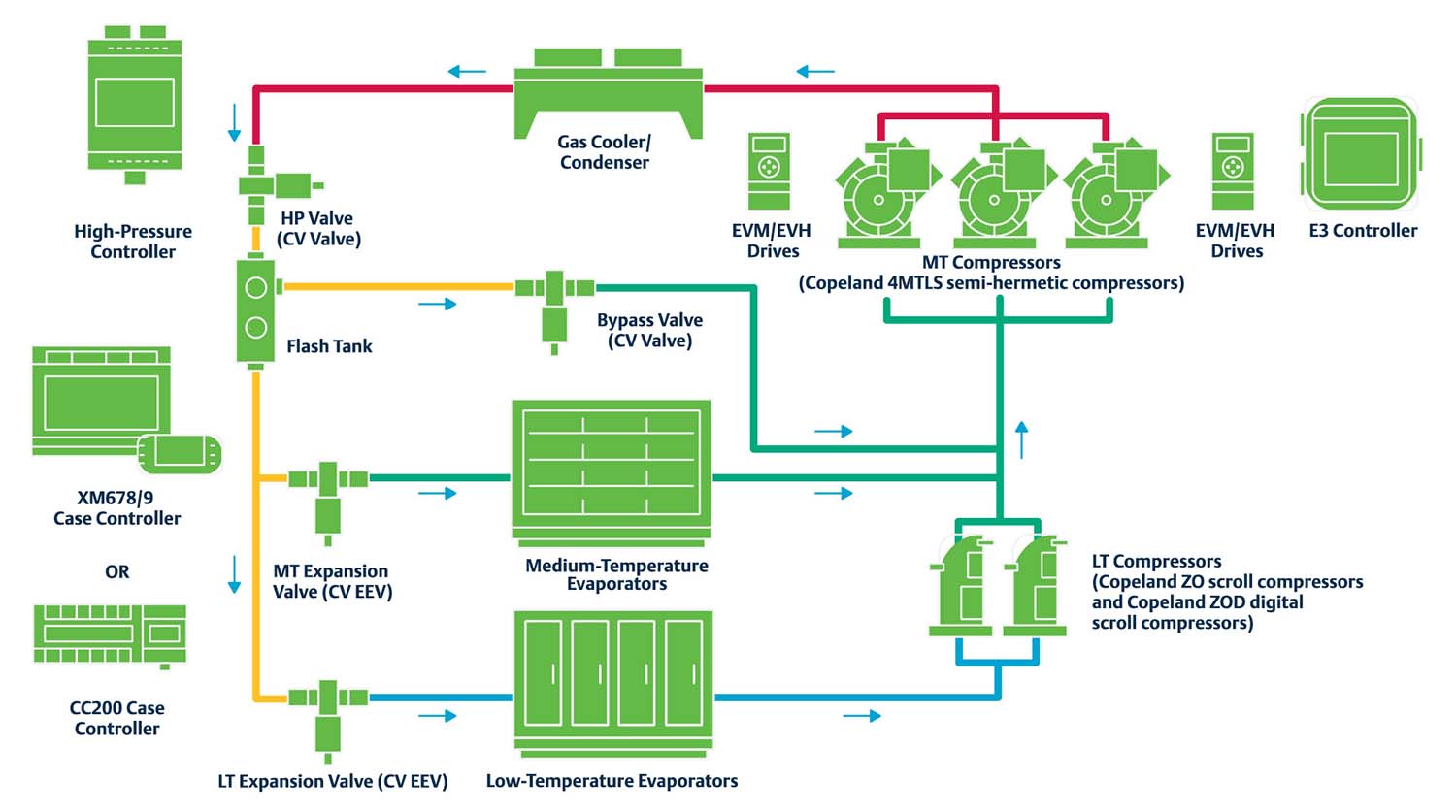
1. Booster design — CO2 TCB systems run on R-744 for both medium- (MT) and low-temperature (LT) refrigeration loads. Instead of LT compressors discharging refrigerant into the condenser, LT compressors discharge R-744 into the MT compressors, which boost the refrigerant to a gas cooler.
2. Gas cooler (aka condenser) — The gas cooler (on the roof) must be sized to handle the system’s total heat of rejection from MT compressors per installation design conditions. Variable-speed fan motor control is typically deployed, and adiabatic cooling pads can be used to improve system efficiencies in warm ambient climates.
3. High operating pressures — CO2 TCB system operating pressures can exceed 1,400 psi when MT compressors discharge into the gas cooler on a hot summer day (e.g., 100 °F). MT discharge lines must be constructed with stainless steel or special ferrous alloy copper to handle these pressures.
4. Low critical point of 87.8 °F — Below the critical point, R-744 is at saturation and the system operates in subcritical mode. When the ambient temperature rises above ~75 °F, refrigerant exits the gas cooler as a supercritical fluid (at or above 87.8 °F) and the system enters transcritical mode.
5. High-pressure valve — As R-744 exits the gas cooler, its pressures must be reduced before being reintroduced to the refrigeration circuits. A high-pressure valve (HPV) reduces the refrigerant to around 550 psi and transfers it to a receiver (aka flash tank) that separates vapor from liquid.
6. Flash tank (aka receiver) — The flash tank receives a mixture of vapor and liquid refrigerant at around 40 °F equivalent saturation, with vapor rising to the top and liquid settling at the bottom. Liquid is circulated through insulated lines that feed the MT and LT cases (as low as -20 °F) equipped with electronic expansion valves (EEVs). Vapor is fed through a bypass gas valve (BGV) and bypass line.
7. Reliance on electronics — Because of R-744’s potential reactivity to various conditions, electronic controls are required to: manage system pressures; control variable fan speeds; modulate HPVs, BGVs and EEVs; maintain consistent flash tank pressure; and provide smooth compressor staging.
8. High triple point (-69.8 °F and 60.4 psig) — When charging with liquid while system pressures are below the triple point of 60.4 psig, R-744 turns into dry ice, stops the refrigerant flow, and causes a variety of potential system problems. Technicians should charge with vapor until the system reaches 100 psig.
9. Rising standstill pressures — Managing rising system pressures during power outages or planned shutdowns is an important CO2 TCB design consideration. Technicians must understand the maximum pressure ratings of cases, valves, evaporators and all system components.
10. System safeties and pressure-relief valves — High-pressure safety and/or mitigation strategies provide system- and compressor-specific protection. Pressure-relief or isolation valves should be installed in various system sections to prevent a full loss of refrigerant charge. Refrigerant should be vented outdoors per applicable codes.

Report Abusive Comment