The compressor should never pump liquid. This not only damages the compressor, but it also can create a potential safety hazard.
Similar to the human heart, the refrigeration compressor needs to be properly maintained and requires periodic inspection and testing. Unfortunately, the compressor is often ignored until it malfunctions or stops running altogether, at which time it gets replaced and the system is back up and running - temporarily. Often the culprit is not the compressor, but a system failure or design problem with accessory equipment that killed the compressor prematurely.
Below are steps to follow for troubleshooting a compressor and the associated problems that can cause a system to fail prematurely.
SUCTION AND DISCHARGE PRESSURE
Both the suction and discharge pressures at the compressor are normally measured with a standard set of refrigeration gauges. An explanation of how to measure both pressures on the suction and high side of the system with a digital multimeter (DMM) and a pressure/vacuum module, with or without standard gauges is included here. If the gauges are left on the system and used in conjunction with this test, the module will verify the accuracy of the standard manifold gauges.To measure the pressures on your DMM in conjunction with standard manifold gauges:
1. Attach the pressure/vacuum module hose fitting to the refrigerant service hose on the manifold gauge set (usually the yellow hose).
2. Attach the pressure/vacuum module to a DMM and set the module function to cm/in. Hg.
3. Install the blue and red hoses to the suction side and high side of the system, just as during any normal service process.
To read suction pressure on the DMM, open the blue handle on the manifold gauges. This puts the system suction pressure into the pressure/vacuum module. Read the pressure on the digital readout and compare it to the gauge pressures. Don't be alarmed if the pressures don't match exactly. Today's DMMs, like the Fluke PV350, are typically much more accurate than a standard set of refrigeration gauges.
To read the discharge pressure on the DMM, close the blue valve on the gauges and open the red handle on the manifold gauges. This puts the system discharge pressure into the module.
To remove the module, reverse the process followed when installing the unit.
(Caution: Be sure to close the high-side port of the gauges first, and remove the refrigerant from the high-side gauge by allowing the compressor to run and pull excess refrigerant into the low side of the system.)
To measure the pressures on the DMM and pressure/vacuum module without installing the manifold gauges:
1. Attach the module hose fitting to any standard refrigerant service hose.
2. Connect the refrigeration hose to the service port on the compressor.
3. Open up the service port and read the refrigerant pressure directly on the pressure/vacuum module.
It is possible to read one pressure at a time using a single pressure/vacuum module. Technicians will need to record the suction or discharge pressure one at a time. Or, if using a DMM with a minimum/maximum (min/max) feature, such as a Fluke 179, they can record the suction pressure as the minimum value, then record the discharge pressure as the maximum value.
To remove the pressure/vacuum module, reverse the process followed when installing the unit. (Caution: Be careful when removing the high-side port of the gauges as it can be under very high pressure.)
To minimize refrigerant loss, learn to practice safe refrigerant-handling habits when removing the module from the high side of the system. Shut off the compressor prior to gauge removal and allow the pressure to equalize. When removing the gauge from the low side of the system, it is not necessary to shut down the compressor first.

COMPRESSOR DISCHARGE LINE TEMPERATURES
Pressure and temperature are fundamental tests that can be performed to determine what is happening inside the compressor.To measure the temperature of the compressor, take the following steps:
High-temperature conditions can be caused by high condensing temperatures/pressures, insufficient refrigerant charge, noncondensibles within the system, high superheat from the evaporator, restricted suction line filters, or low suction pressure. These conditions cause the compressor to have a higher-than-normal compression ratio, work harder, generate hotter internal hermetic motor windings, and as a result, cause compressor wear, fatigue, and failure.
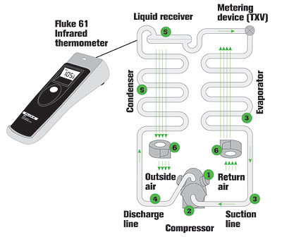
A temperature survey is a critical part of the service technicians' job. A quick check of a system's components not only helps diagnose troubles, but also allows the technician to anticipate failures by regular monitoring of critical temperatures. Use an infrared thermometer to do a quick survey of: compressor head temperatures; compressor oil sump temperatures; evaporator coil and suction line temperatures; discharge line temperatures; condenser coil and liquid line temperatures; and fan motor temperatures.
Technicians can quickly survey a refrigeration system by scanning the temperatures of various components with an infrared (IR) thermometer (see Figure 1). While touching each component may do this, a noncontact infrared tool is faster and much more accurate. By keeping good records, technicians may detect trends that indicate impending failure.
(Note: IR instruments read best when they are measuring an object with a dull surface. If the surface is shiny, dull it with black markers, nongloss paint, masking tape, electrical tape, etc.)
RECORDING TEMPERATURE OVERNIGHT
When working on refrigeration systems, it is often useful to record temperatures in the refrigerated space. This enables technicians to detect problems that would go unnoticed with a single system check.By recording min/max temperatures in key locations over a period of time, technicians can make sure that air circulation and refrigeration capacity meet the application's requirements. Digital recording thermometers allow these temperatures to be recorded over extended periods of time. Some DMMs can also measure min/max of a single temperature, and have the benefit of a 100-hour relative time stamp to record when the min/max occurred. Dual channels can record two temperatures at the same time.
Being able to record temperature differences across a coil for extended periods of time comes in handy for troubleshooting erratic problems where the technician may not be able to wait until the problem occurs.
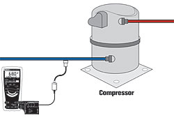
COMPRESSOR VALVE PERFORMANCE
The following method can be used to test for internal valve leakage in small hermetic and semihermetic compressors used in medium- and low-temperature applications. (See Figure 2.)1. Attach a pressure/vacuum module to a DMM and set the module to cm/in. Hg.
2. Connect the module at the suction line service port.
3. Close the compressor off from the low side of the system by front seating the suction service valve.
4. Run the compressor two minutes.
5. Turn off the compressor and observe the reading. It should have pulled down to at least 16 inches (410 mm) of Hg. If the vacuum reading starts weakening toward 10 inches (254 mm) of Hg vacuum, the discharge valves of the compressor may be leaking and will probably need to be replaced.
If the compressor doesn't pull a vacuum below 16 inches Hg, the suction valves are weakening and may need to be replaced. If the compressor is welded or hermetically sealed and these conditions exist, a new compressor is the only possible remedy.
(Caution: Whenever replacing a compressor with faulty valves, be sure to diagnose the complete refrigeration system before and after a new compressor is installed to avoid repeat compressor failures.)
Duane Smith is a Fluke specialist on digital multimeters. A 30-year veteran, Smith trains test tool users, troubleshoots field applications, and helps develop new DMMs and electrical testers. He may be contacted at 425-446-5681; duane.smith@fluke.com.
Publication date: 05/15/2006

Report Abusive Comment