This article is part two of a three-part series on inspecting and servicing gas appliances. The information contained throughout this article series follows the gas furnace check sheet provided in the PDF link below. (Click on the link "Equipment Check Sheet" at the bottom of this article.) I would recommend that you make several copies of this check sheet to use on jobs as a reference source.
Thermostats/Zone Sensors
The thermostat is a temperature-controlled switch. It may or may not have selector switches for heating/cooling or fan operation. Some are still mechanical, but the majority are now digital. Some of the most common thermostat types are listed below:
- Heating only (mechanical or programmable)
- Cooling only (mechanical or programmable)
- Heat/cool (mechanical or programmable)
- Heat/cool digital nonprogrammable
- Heat/cool programmable
- Heat pump (mechanical or programmable)
- Heat pump digital nonprogrammable
- Heat pump programmable
- Heat/cool/humidity (mechanical or programmable)
- Line voltage (single or double pole, and single or multi-stage)
- Pneumatic (direct acting or indirect)
- Zone sensors (programmable or nonprogrammable)
Unless you are using a zone sensor (usually found in commercial applications), thermostats follow an industry standard for wiring and operation. Connect the correct color between the stat and the unit terminal strip and you are good to go. Depending on the application and the type of stat you will find the following:
Standard heating only:
R - (red) 24-volt hot lead from the low voltage transformer
W - (white) First stage heatingHeat/cool (programmable or nonprogrammable):
R - (red) 24-volt hot lead from the low voltage transformer
W - (white) First stage heating
Y - (yellow) First stage cooling
G - (green) System blower
C- (black) 24-volt common from the low voltage transformer (required by some manufactures to power the thermostat)Heat/cool (programmable or nonprogrammable) multi-stage:
R - (red) 24-volt hot lead from the low voltage transformer
W - (white) First stage heating
Y - (yellow) First stage cooling
G - (green) System blower
C - (black) 24-volt common from the low voltage transformer (required by some manufactures to power the thermostat)
W2 - (blue) Second stage heat
Y2 - (orange or brown) Second stage cooling (if used)
C - (black) 24-volt common from the low voltage transformerHeat pump, line voltage, pneumatic, or zone sensor:
Consult the manufacturer. There are many variations of thermostats and sensors available.Testing Procedures:
When testing the thermostat, always record the settings before adjusting so you can return it to its original position. It is good practice to always set the thermostat 10 degrees above or below the set point when testing the equipment to eliminate the recording step; you just have to lower or raise it by 10 degrees when you are done. The heating or cooling should start if the equipment is on. Remove the cover and blow out any dust that may have accumulated in the stat. For test purposes, the thermostat can be bypassed by removing the thermostat from the sub-base and using jumper wires at the terminals or by jumpering out the stat at the equipment terminal strip.Caution: Never jumper R-C or the terminals on the gas valve. Permanent damage to the transformer, fuse, or thermostat could result.
Jumpering the following terminals should result in the sequences below:
R-W - Heat sequence starts.
R-Y - Cooling condenser starts and system blower starts on some newer systems.
R-G - Fan starts in circulation mode or cooling mode.
R-W1 and W2 - Both first and second stage heating operate. (W2 by itself will not operate unit.)
R-Y1 and Y2 - Second stage cooling will operate. Some manufactures will slow the system blower by 20 percent in place of a two-stage condenser to allow for higher latent load capability of the evaporator coil.
Note: Always count your jumper wires before you leave to make sure you didn't leave one on.
Location/Mounting:
The thermostat should be located on an interior wall as close to a cold air return as possible. It should not be located where the sun or heat sources such as lamps or TVs can affect it. The stat should be located from 4.5 to 5 feet above the floor depending on customer height (not yours).Always securely fasten the thermostat to the wall with screws and plastic anchors if needed. Always make sure that the thermostat is installed level, as older stats will not be properly calibrated if they are out of level, and any thermostat installation looks poor if not level. Neatly tuck the wires into the hole in the wall and use a piece of thumb gum or insulation to stop cold drafts from coming into the stat from the cool interior space in the wall. Always use 18 gauge or larger wires for the thermostat; smaller wires cause high amp draws and break easily.
Heat Anticipator Adjustment:
Older types of thermostats require that the heat anticipator be set. The heat anticipator is designed to shut off the appliance 2-3 degrees before it reaches the room set point, allowing the residual heat in the heat exchanger to bring the room up to the exact set point, avoiding overshooting. Newer thermostats use cycle timing to achieve the same thing. If the manufacturer has a prescribed setting, use it; if not, follow the procedure below. Improper setting of the heat anticipator will result in reduced comfort and/or equipment short cycling and reduced equipment lifespan.Setting The Heat Anticipator:
Remove the thermostat from the sub-base. Jumper R-W. With a high-resolution clamp-on ammeter or milliamp meter measure the current draw through the jumper wire of the gas train during the heating sequence - usually from 0.12-1.2 amps. (Do not take a final reading until the blower has started.) Set the heat anticipator to the current setting that matches the reading on your meter. Reinstall the thermostat and cycle the appliance in all operating modes. (Do not operate the air conditioner in the winter as compressor damage could result.) Cycle times on newer thermostats usually do not need to be adjusted; however, if they do, consult the manufacturer's literature. Some thermostat models employ a cooling anticipator, which turns the cooling equipment on early to start the cooling process. This is a fixed anticipator and therefore does not require adjustment.Filters
In general, when checking the filters, you are looking for cleanliness, proper size, and correct flow. It is important to make sure that the type of filter used meets the needs of the occupant of the dwelling. Better filtering systems can remove pet dander, dust mites, viruses, bacteria, tobacco smoke, and aerosols, along with normal contaminants like dirt, hair, and lint. It is especially important to change the filters more frequently after construction or remodeling.On media type air filters it is good practice to check the pressure drop across the media when it is new to have a reference point to change the filter when the pressure drop becomes excessive. This method will not work with electronic air cleaners as they become less efficient as they become dirtier, and a visual inspection and regular cleaning become very important. Always check the filter rack to assure a seal is formed around the filter and the duct. Air leaking in the filter rack can cause a negative pressure at the appliance that will affect the combustion or ventilation air requirements.
 A digital manometer has many uses including checking the cut in and cut out of the pressure switch.
Blower Compartment
The prime air mover or furnace blower is the fan that moves heat by convection through the conditioned space. The blower assembly is made up of a wheel or squirrel cage, the blower housing, and a motor, or motor pulleys and belt on a belt drive system.The furnace blower must overcome the resistance of the filter, heat exchanger, evaporator coil if installed, the supply air ducting and register, and the return air ducting and registers. The amount of work the blower can do is rated in inches wc (inches water column) shown as external static pressure on the manufacturer's label - usually 0.50 inches wc. The term external static pressure is used because manufacturers have already calculated the pressure the heat exchanger and a standard filter will use, and this is the pressure left over.
The furnace blower speed must be set according to the temperature rise shown on the manufacturer's data plate in the furnace. The temperature rise should ideally fall in the upper middle of the range. The temperature rise should be checked during every startup and service period. It should also be checked if the type of filter used is changed, or dampers are adjusted.
To set the heating rise, use the following procedure:
1. Find the temperature rise range on the manufacturer's data label.
2. Determine the center of the range. For example, for a 40-70 degree range, the center is 55 degrees.
3. Operate the furnace in the heating mode for a minimum of 10 minutes, or until the supply air temperature has stabilized and stopped rising.
4. Using an accurate thermometer, out of line of sight of the heat exchanger, measure the supply air (SA) temperature and the return air (RA) temperature.
5. SA - RA = temperature rise.
6. If the rise is outside of the center of the range, raise or lower the blower speed to obtain the correct rise. Lower blower speeds will give a higher temperature rise. Let the temperature stabilize between each reading.
Do not power multiple speeds on the motor at once or motor failure will result.
Verify the voltage to the motor and the measured amperage. Make sure that both fall within the required range. Information on the blower is found on the manufacturer's label and/or the motor. If the motor is not OEM, the data from the motor must be referenced. Shut off the appliance and lock out the power source. Make sure that the wheel and motor end are clean. If not, remove the blower assembly and clean it with a brush and a vacuum cleaner. If the appliance has a belt drive blower, inspect the pulleys for proper alignment, and remove and check the belt for cracks or glazing. Also take hold of the blower and/or motor shaft and feel for play in the bearings. There should be some play parallel to the shaft (thrust), but there should be no play perpendicular to the shaft.
Clean the inside of the blower compartment with a vacuum and a shop rag to remove dirt and debris that may have made it past the filter.
 In this furnace, the resistance between the neutral and ground was very high. The problem was traced back to a loose wire in the breaker panel.
Wiring
During new equipment startup and service, the appliance wiring should be checked from the breaker through all connections into the furnace for loose connections, proper sizing, and proper installation. Check the incoming voltage, and make sure that it falls within the specified range on the appliance. Every installation should include a service switch or disconnect at 3-4 feet to eye level off the ground, usually mounted to, or close to, the appliance. Make sure that a switch cover is installed.It is imperative that the polarity be checked on all equipment. This means that the hot (120-volt black wire) is carrying 120 volts to the hot (120-volt black wire) on the furnace. The neutral should also be checked. With the furnace off, measure the resistance between the neutral (white wire, 0-volt potential) and any earth ground (metal); the resistance should be less than 2 ohms. Using a voltmeter with the power energized, verify the phasing of the line and low voltage transformer. From the hot (L1) (I usually measure the hot at the door switch terminal) to R on the transformer, the voltage should read 96 volts. If the polarity is reversed, the voltage will read 146 volts. Check to make sure that the ground is securely fastened. Record the operating voltage and the system amps. Finally, make sure that the equipment does not operate with the blower door removed.
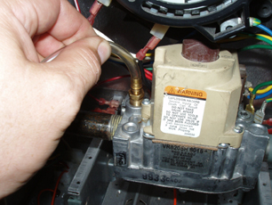 When threading the pressure test fitting into the gas valve, hold the hose and gently start the fitting. It is very easy to cross thread the aluminum threads in the gas valve.
Burner Compartment
At every inspection record the Btuh input for the appliance. Some of the checks require that you know this value for calculations.Note: Anytime air shutters are adjusted, fuel pressure is changed, burners are removed and reinstalled, venting or combustion air is modified, blower speed is changed or any other parameter on the furnace is adjusted that could directly or indirectly affect the combustion process, a combustion analysis should be performed. A combustion check should also be performed at each inspection to assure safety of the customer and stability of the O2 and CO readings during operation. CO in the stack should never exceed 400 ppm during normal operation. If the CO at the furnace is above 100 ppm, corrective action should be taken.
Burners:
General information: In order for proper combustion to take place, the fuel and air must be mixed before combustion. In order for the fuel to mix efficiently, all burners are designed with a venturi, which works on the principal that a high velocity gas will create a negative pressure perpendicular to the gas flow, drawing air (primary air) into the burner and mixing it with the fuel before combustion takes place. If the fuel-air mixture is too lean, the gas will not ignite, and if it is too rich, the mixture will soot when burned.After ignition occurs at the burner head, additional air (secondary air) is drawn into the combustion chamber from the flue gases rapidly moving through the heat exchanger due to their natural buoyancy. Secondary air helps to ensure complete combustion. Too much secondary air reduces the efficiency of the furnace. On high efficiency furnaces, the secondary air is kept to a minimum to achieve higher combustion efficiencies.
Older burners have a primary air shutter that should be adjusted toward the open position if there is any yellow in the flame at all. The flame should be a dark outer blue with a light blue inner cone. Orange in the flame indicates dust, and need not cause alarm or concern. The burners should be pulled and cleaned annually to maintain peak efficiency.
Every furnace with multiple burners has a carryover to light the adjacent burner in the next cell. When lighting off the furnace, watch each of the burners to assure that smooth ignition occurs. Always stand to the side when lighting off the furnace to assure that you are not victim of a roll out if one were to occur. Many times small spider webs or rust will clog a carryover, causing delayed ignition and roll out. After cleaning the burners with water, blow out the burner and carryover with air to assure that the water is not clogging the burners, as the gas pressure in the manifold will not always push the water out of the burner.
Orifices:
The function of the orifice is to meter the gas into the burner in conjunction with the manifold pressure. The orifice is usually made of brass and requires little to no maintenance. Each orifice is designed differently for each style of furnace and therefore they are not interchangeable between manufacturers.During new equipment installation the orifices should be checked for correct size (number stamped on front or side of orifice). The orifices are sized in Btu per hour and, if over- or under-sized, will over-fire or under-fire the furnace.
The Gas Valve:
The gas valve starts and stops the flow of gas to the main burners. The valve can be single, two stage, or modulating. Modern valves incorporate a manual control, gas supply and adjustment for the pilot, pressure regulator, and redundant (duel solenoids) for extra safety and to start and stop the flow of gas. Many incorporate a CPU to control the furnace operating sequence and lighting procedures and flame proving system (such as the Honeywell Smart Valve®).The Pressure Regulator:
Gas supplied to a residence is usually supplied at a pressure of 10-14 inches of water column. Inches of water column are used to measure pressures below 1 psig (1 psig = 28 inches wc). Most residential appliances operate at a manifold pressure of 3-4 inches wc, with the most common pressure being 3.5 inches wc. The pressure regulator is used to reduce the higher-pressure gas to the manifold requirements of the manufacturer.Most valves today have the regulator built into the valve, but older wild pilot systems and commercial systems can have a separate regulator. When adjusting the regulator, turning clockwise increases pressure on the regulator, raising the gas pressure to the manifold, and counterclockwise decreases the manifold pressure. When adjusting the pressure on a sealed combustion system, it may be necessary to follow specific manufacturer's instructions because of negative pressure on the burner box or enclosure.
Incoming And Manifold Pressure:
The incoming pressure of the gas must always be checked at furnace startup and inspection. The pressure should be from 7 inches to 14 inches of water column and a minimum of 5 inches in most cases for the regulator to operate properly. If the gas is outside of the 7-10 inches range, call the utility company if required in your area to have it reset; if not, adjust the regulator located before the gas meter. (It is not uncommon for moisture in the gas to freeze the regulator in inclement weather. If this happens contact the utility to make the repair.)The manifold pressure must be set as specified by the manufacturer. The pressure usually runs from 3-4 inches wc. If the manifold pressure is outside of this range, it can damage the furnace. If the furnace over-fires, the flame can cause impingement, generating cracking, sooting, and/or CO production. Under-firing can cause condensing and low heat output.
The Pilot Assembly:
The purpose of the pilot is to ignite the main gas quickly and safely. All pilots incorporate a flame sensing or proving device to prove the pilot is lit before the main gas is allowed to open. The sensor could be a thermocouple, a bimetal sensor, a power pile, a liquid filled sensor (mercury switch), or a flame rod. The function is always the same - to break the circuit to the main gas valve if a pilot is not sensed.There are two different types of pilots: aerated, which mixes gas and air before the burner, and non-aerated, which uses secondary air only to burn. Most pilots are non-aerated which means the only dirt that enters the pilot is through the gas line. These pilots require less maintenance and occasional replacement of the orifice. Removing the orifice, filling it with water, and tapping the water through the orifice where it connects to the pilot tubing can clean the pilot orifice. Never try to clean the orifice with a pin or wire object as it could distort the holes increasing gas flow to the pilot burner.
There are also two types of pilot systems used: standing pilot, where the pilot is always burning, and intermittent pilot, where the pilot lights only when there is a call for heat.
Most standing pilot systems incorporate a thermocouple as a pilot-sensing device. A thermocouple is a thermoelectric device that generates electricity when the hot junction is heated by the pilot flame. The thermocouple generates about 30 mv DC under no load and 12-18 mv DC under a load.
If the thermocouple output is low, check the following:
1. Make sure the pilot is clean.
2. Make sure only the top 1/2 inch of the thermocouple is hitting the flame. A flame hitting the center will not work or cause nuisance shutdowns.
3. Make sure that the thermocouple is snug in the gas valve (hand tight + 1/4 turn).
4. Replace the thermocouple.
The thermocouple uses the electricity to hold open a solenoid allowing gas to continue to flow to the pilot. Some older systems incorporated a wild pilot system where the pilot gas had to be manually shut off, and the solenoid controlled gas flow to the main burner directly. The pilot safety must stop all gas flow to the main burner WITHIN THREE MINUTES from the time the pilot is removed from the thermocouple.
Flame sensing devices use flame rectification to prove flame. Rectification works off the principal that a flame conducts electricity (although not very well). A small electrode is used with a large grounding surface allowing the AC current to travel out easily, but because of the small amount of surface on the electrode the AC signal does not travel back. This produces a half rectified AC wave or effectively a DC signal. The strength of the DC signal is measured in DC micro amps or DC ma. The minimum signal usually is 1-1.5 ma. The signal is measured by connecting a micro amp meter in series with the flame rod.
If the flame signal is poor, check the following:
1. Check the condition of the grounds. Measure between neutral and ground with an ohmmeter set to the lowest setting. The resistance should be less than 2 ohms. If the resistance is higher, check the neutral and ground back to the box.
2. Measure the resistance between the burners and the ground wire. It should also be less than 2 ohms. If high, try installing a ground wire as close to the burners as possible.
3. Clean the flame rod with steel wool or a Scotchbrite® pad. Do not use sandpaper, as it will scratch the rod causing a buildup of glass from sand and dust.
4. Replace the flame rod.
5. Verify the voltage coming from the control with the manufacturer and, if needed, replace the control.
Indirect ignition systems sometimes use spark ignition to light the pilot. These assemblies have an electrode encased in ceramic as an insulator. If the ceramic has failed or is failing, the spark (usually 8,000-12,000 volts DC) can travel to ground causing the pilot not to light. If this happens, the igniter must be replaced.
Most flame sensors will respond within two to six seconds depending on the system. Most have multiple tries for ignition before a lockout will occur.
Delayed Ignition:
Delayed ignition occurs when the main burners do not ignite within the four-second requirement. Delayed ignition can be extreme enough to cause a small explosion shooting flames out from the furnace.If a customer claims to have a delayed ignition problem, inspect and repair the problem before you test the furnace. This is one of the only times a repair is suggested prior to cycling the unit because of the danger of explosion during appliance operation.
If delayed ignition occurs, check the following:
CAUTION: Stand to the side when testing a delayed ignition problem. The flame could roll out causing severe burns or death.
1. Look to see that the pilot location is correct and the pilot size is sufficient.
2. Ensure that the carryover on the burners is clean and aligned with the adjoining burners.
James L. Bergmann is an HVAC/R Technical Specialist with Testo Inc. and also an instructor at Cuyahoga Valley Career Center in Brecksville Ohio. For more information, e-mail jbergmann@testo.com or visit www.testo.com.
Publication date: 11/14/2005
CLICK HERE for Equipment Check Sheet.

Report Abusive Comment