The easiest way to understand DDC controls is to compare them to pneumatic controls. Most contractors have been around pneumatic systems and are familiar with the components.
Also, one can see a direct cause and effect - a varying air pressure signal moves a spring-loaded bellows, or diaphragm, which positions a valve or damper. In DDC, all this is done electronically in a mysterious "black box." But when you compare the two systems, you will find that the mechanical part of DDC is simpler than you thought.
This article will compare a pneumatic control system to the same system with DDC, focusing on the basic subsystems.
Basics Of Controls
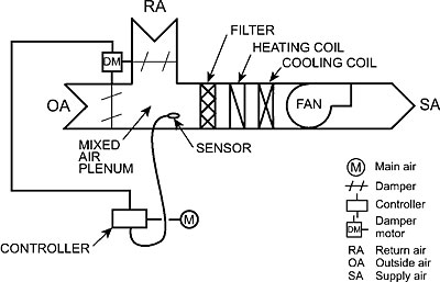
HVAC defines the three basic subsystems:Each of these subsystems has four basic components. Figure 1 shows a damper control subsystem for a basic single-zone system to illustrate the four basic components:
1. The sensor in the plenum senses the mixed air temperature and sends a signal to the controller.
2. The controller receives information from the sensor and sends the appropriate air pressure signal to the actuator. The actuator is the damper motor.
3. The actuator positions the controlled device to regulate the air. In Figure 1, the damper motor modulates the two air dampers.
4. The controlled device is the return air (RA) and outside air (OA) dampers, which modulate to regulate the temperature of the air in the mixed air plenum.
Complete Single-Zone System
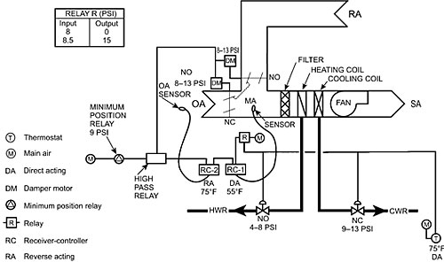
Figure 2 shows a more extensive control system for a single-zone HVAC system. It has the usual subsystems:The heating control subsystem consists of the thermostat (T) and the automatic control valve in the hot water return (HWR) piping.
1. The thermostat is the sensor and controller for the subsystem. It is supplied with main air pressure from the compressor, senses the room temperature, and controls the output air pressure that is sent to the control system. The set point of the thermostat is the room temperature to be maintained.
In Figure 2, the thermostat is marked DA, 75 degrees F. "DA" means direct acting - as the space air temperature increases, the output signal from the thermostat increases. The set point of the thermostat is 75 degrees.
2. The automatic control valve is the actuator and the controlled device. It regulates the flow of hot water through the heating coil. See the notation at the valve: NO, 4-8 psi. This means it is open when there is no air pressure and modulates towards closed at a pressure of 4 psi or more and is fully closed at 8 psi.

Cooling Control Subsystem
The cooling control subsystem is the thermostat and the automatic control valve in the chilled-water return (CWR) piping. The valve regulates the flow of chilled water through the cooling coil. It is labeled NC 9-13 psi, so it is closed until the thermostat sends a 9-psi signal and is full open at 13 psi.In regard to the damper control subsystem, it starts with RC-1. It's the same basic system as in Figure 1 (sensor, controller, actuator, and controlled device). It simply has a few more gadgets to provide a more sophisticated control of the air:
1. Receiver-controller RC-1 receives an input signal from the mixed air (MA) sensor. It relays an output pressure signal to the damper motors to operate the dampers. Note that RC-1 is labeled DA 55 degrees. It is direct acting, and the 55 degrees means that the air dampers are modulated to maintain an MA temperature of 55 degrees.
2. Receiver-controller RC-2 receives an input signal from RC-1 and information from the outside air temperature sensor. It controls an economizer cycle, a cycle that uses outside air for cooling when practical. RC-2 is marked RA, 75 degrees, which means it's reverse acting - as the temperature increases, the output signal from RC-2 decreases. At 75 degrees and above, the signal from RC-2 is 0 psi. When the OA temperature drops below 75 degrees, the signal from RC-2 increases from 8 to 13 psi.
Now look at the OA damper motor and damper. The motor is labeled as operating between 8 to 13 psi and the damper itself is marked NC (normally closed). The result is that below 75 degrees the OA damper is modulated so that the outside air can be used for cooling. Above 75 degrees (0-psi signal) the damper is at minimum air position.
3. The high-pass relay is really a selector switch. It selects the signals from RC-1, RC-2, and the minimum position switch and relays the one that is highest.
4. The minimum-position switch always sends a 9-psi signal to the high-pass relay. This makes sure that the OA damper will never be fully closed so that the requirement of minimum outside air is met.
Relay R
Now look back to just before RC-1 to relay R. It is a signal booster. The volume of air from the thermostat may not be sufficient to operate the controls during the cooling mode. So relay R receives a main air signal as well as the signal from the thermostat. The schedule in the upper left of Figure 2 shows its operation.When relay R receives an 8-psi signal, the heating valve is closed. But relay R is sending 0 psi to RC-1. This means that the OA damper is in the minimum air position during the heating mode.
When relay R receives 8.5 psi or higher, RC-1 receives a 15-psi signal. This means that the OA and RA dampers are modulating to utilize the economizer cycle for the mixed air temperature. At a 9-psi signal, the cooling valve begins to provide cooling.
Direct Digital Control Systems
For HVAC, a DDC system is much simpler than a pneumatic system. One can compare DDC to calculators. The calculator does all the complex processes of multiplication, division, and extracting square root for us. All we have to do is learn what buttons to push. With DDC, you have to learn how to operate the computer program that controls the system.Compare Figure 2 (a single-zone pneumatic system) with Figure 3, which is a similar system that is controlled by a DDC system. The mechanical operations of modulating dampers and valves are still the same. But the complex system of relays, receiver-controllers, high-pass relay, and minimum position relay in Figure 2 is eliminated. All of these functions are performed within the controller.
Wiring from sensors carry input signals to the controller. Other wires from the controller carry output signals to operate the damper and valve actuators to open, close, or modulate them under the proper conditions. The sensors are electronic devices and the damper and valve actuators are electrically operated.
Instead of air pressure signals, the controller sends and receives two kinds of electronic signals to the actuators, and from the sensors:
1. Digital (on or off).
DO: Digital output signal.
DI: Digital input signal.
2. Analog (varying). The varying psi branch signal in a pneumatic control signal is an example of an analog signal.
AO: Analog output signal.
AI: Analog input signal.
A computer communicates with the controller to receive, store, and process data. The computer is programmed to direct the controller for the sequence of operations for the HVAC system in that particular building. It can be directed to send commands to the controller, such as changing set points.
In addition, the computer can print out operating data for any component of the system. This means that you can get all the information from the computer that you need to identify problems and their probable cause. So you don't have to test individual components in the mechanical room. Usually you can also make changes in the control parameters of the variables, such as temperature and times.
To make changes in the program that controls the sequence of operations, a password is required. This ensures that only qualified people work on the program of operations.
The greatest problem with digital control systems is the lack of qualified technicians to operate and maintain them. A DDC technician should be well versed in the following areas:
1. HVAC system understanding.
2. Control system understanding.
3. Computer literacy.
At present, many technicians are very knowledgeable in one of these areas, but few are competent in all three.
Adapted from Control System Basics for HVAC Technicians by Leo A. Meyer, published by LAMA Books (www.lamabooks.com). A companion book, Direct Digital Controls for HVAC Technicians, is expected to be released winter 2006.

Sidebar: A Control Which Has Been A Hit
While direct digital controls may be the systems of the future, Bryant Heating and Cooling Systems believes its Evolutionâ„¢ Control, introduced in early 2004, is a hit today. And, it said, it has the feedback to prove it."The Bryant Evolution System provides user-friendly, efficient operation, energy savings and maintenance, giving the homeowner comfort never before possible," said Debbie Castro, marketing manager for Bryant. "In addition, the system is so easy to program, dealers will receive fewer callbacks, improving their customers' satisfaction.
"With our usual ‘whatever it takes' attitude, Bryant created a product that surpasses both homeowner and dealer expectations. That's just one of the reasons why Bryant received The News' Dealer Design Award in 2004."
The Evolution System is designed to integrate all of Bryant's HVAC units and accessories into one seamless, integrated system powered by the Evolution Control. Bryant said its product is the first HVAC system to use a single control to integrate and manage all six comfort functions: temperature, humidity, air flow, ventilation, indoor air quality, and zoning. In addition, the Evolution Control includes a large, easy-to-read backlit display, user-friendly programmability, and advanced communication capabilities that go as far as to advise times for regular maintenance and filter changes, it said.
There are a number of reasons why this product has been a hit with dealers. According to Bryant, the time required for system installation is reduced by at least 10 percent "compared to previous systems with programmable controllers." Startup is also simplified because, once activated, the Evolution Control is designed to automatically configure itself to the system and components. System-wide diagnostics also are provided via the control panel in text message instead of numerical codes that require a manual to interpret.
"You have to be sold on Evolution yourself before you can sell it to others. I'd encourage any dealer who isn't selling it already to install and test it in his own house," said Bill Krestakos, vice president of sales at Schaafsma Heating and Cooling, Grand Rapids, Mich. "We also were somewhat skeptical. Bryant said the product was going to be ‘revolutionary.' That's a big word - a big promise. But, it has met our expectations from day one. We've been selling the Evolution Control since it first became available, and we've only sold one variable-speed system without it."
Publication date: 09/26/2005

Report Abusive Comment