Designing A System
An engineer designs a duct system to take system effect into account and to avoid as much system effect as possible.The designer first calculates the system resistance. This is the amount of resistance to airflow (static pressure) that the system will impose, measured in inches of water gauge (inches wg). The system resistance depends upon these factors:
After the system resistance is calculated, the designer calculates the system effect factor. This is based on the configuration of the fan connection to the system as compared to the ideal situation under which the fan was tested. This system effect factor is based on the use of charts and graphs, such as those in the books Fans and Systems published by the Air Movement and Control Association (AMCA) and HVAC Systems Duct Design published by the Sheet Metal and Air Conditioning Contractors' National Association (SMACNA).
Based upon the system effect factor, the equivalent resistance from system effect is determined. The equivalent resistance is added to system resistance to obtain the total system resistance in inches wg. Then the fan is selected from a fan table, based upon the total system resistance, cfm, outlet velocity, and brake horsepower.
Duct At Fan Outlet
The design of the duct at the fan outlet has a great effect on the system performance. Outlet duct is the concern not only of the system designer but also of the technician who may have to modify the system after it is installed.For the most efficient fan performance, the duct at the fan outlet should be straight and the same size as the fan outlet. It should be long enough so that the air velocity becomes uniform across the face of the duct. Achieving a uniform air velocity in the duct involves a process commonly called static regain.
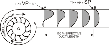
Static regain is the process of converting velocity pressure (VP) to static pressure (SP). Remember that the total pressure (TP) in a duct system is the sum of velocity pressure plus static pressure (TP = VP + SP). Therefore, for a given TP, if the VP is high (usually because the duct area is small), then the static pressure (SP) must be low.
SP is the pressure that causes the air in the duct to flow, and VP is the pressure that results from the air movement. This means that it is desirable to have a high value of static pressure (SP) compared to the total pressure (TP) developed by the fan.
Figure 1 shows the air velocity profiles in a duct at various distances from the outlet of a centrifugal fan. The air in the fan is pushed against the outside of the scroll by the movement of the fan wheel. Therefore, at the fan outlet, there is a high velocity at the top of the fan outlet. However, at the bottom of the fan outlet, there is a negative velocity, because the air is swirling back to the fan at the cut-off, attempting to re-enter the fan.
At point A in Figure 1, the VP is high and the available SP is low. As the air moves down the duct, the velocity of the air becomes more uniform across the duct, and the static pressure increases as the velocity pressure decreases. At point B in Figure 1, the air velocity is uniform across the duct and low compared to the outlet velocity (point A).
Remember that TP = VP + SP. Since the total pressure (TP) in the duct at point B is about the same as it was at point A, as the VP has decreased, the SP has increased. In other words, the system has gained static pressure. This is static regain. The system now has more potential to overcome the resistance in the system and thus the system can deliver more air.
100 Percent-Effective Duct Length
At point B in Figure 1, the air velocity is uniform across the duct area and has slowed. This is the point of highest static regain. The distance from A to B is called the 100 percent-effective duct length. If possible, the fan outlet should be designed with straight duct for the 100 percent effective duct length in order to eliminate system effect at the outlet. The technician should try to maintain straight duct at the outlet. If possible, avoid putting a fitting near the fan outlet.
Calculating the 100 percent-effective duct length depends upon the air velocity at the fan outlet:
100 percent-effective duct length = 2.5 x Duct diameter
100 percent-effective duct length = fpm/1000 x Duct diameter

Figure 2 shows only a part of a table for equivalent duct diameters. For a full table for duct up to 90 inches x 88 inches, see the SMACNA publication HVAC Systems and Duct Design. To use the table (Figure 2), locate one of the duct dimensions in the column on the left, and the other duct dimension in the row at the top. The intersection of the vertical and horizontal columns shows the equivalent diameter. For example, to find the equivalent diameter of a 14-inch x 12-inch duct in the table in Figure 2:
1. Locate 14 in the column on the left.
2. Locate 12 in the row on the top.
3. The intersection of the vertical column and the horizontal row shows 14.2, so the equivalent round duct for a 14-inch x 12-inch duct is a 14.2-inch diameter.

Example:
What is the 100 percent-effective duct length for a fan outlet that measures 20 inches x 14 inches if the air velocity is 3,500 fpm?
1. The table in Figure 2 shows that the equivalent duct diameter for a 20-inch x 14-inch duct is 18.2 inches.
2. Calculate the 100 percent-effective duct length:
100 percent-effective duct length = fpm/1000 x Duct diameter
100 percent-effective duct length = 3,500/1,000 x 18.2 inches
100 percent-effective duct length = 63.7 inches

Even if a 100 percent-effective duct length is not possible, make the straight duct as long as possible. The closer it is to 100 percent-effective duct length, the more static regain occurs. The table in Figure 4 illustrates the percentage of static regain for a centrifugal fan at different percentages of effective duct length. For example, at 50 percent of the effective duct length, the duct has 80 percent of the static regain.

Causes Of System Effect
Even with the most careful calculations, the installed fan will seldom perform exactly according to the design specifications because of system effect (the negative impact on fan performance caused by the duct system). Many unpredictable conditions occur during the system fabrication and installation.Generally, system effect is the result of less than ideal conditions at the fan inlet or outlet. The four most common causes of system effect on the fan are:

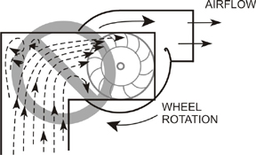
For best fan performance, air should enter the fan inlet at the same velocity across the entire inlet area (Figure 5). With these conditions, all the fan blades can handle the maximum amount of air.
Uneven distribution of air velocity at the inlet (Figure 6) causes turbulence in the fan and less air delivery.
Spinning Air At Fan Inlet
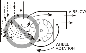
In addition to the air entering the fan at equal velocity across the inlet area, the air should enter the inlet in a straight path. This allows equal distribution of the air to all fan blades. Often improper fan inlet connections cause the air to enter in a spinning motion.
If the spin is opposite the fan rotation (Figure 8), the air volume and pressure may be increased. However, there will also be an increase in the required brake horsepower that is out of proportion. The cost of energy because of the increased horsepower makes it economically impractical. In addition, there will be undesirable air noise.
Obstructions At Inlet Or Outlet
Anything that hinders the airflow at the fan outlet or inlet will have a system effect. Sound attenuation material in the duct that is installed too close to the fan outlet can be blown loose and obstruct the airflow. A fan inlet that is too close to the plenum wall can have restricted airflow.
Material in the fan plenum that does not belong there (such as ladders, boxes, or rolls of insulation) can cause turbulence and restricted airflow that will result in system effect.
On most jobs there is not enough space at the fan outlet to install a straight duct that is equal to a 100 percent-effective duct length. However the duct designer and the duct installer must do everything possible to keep the system effect as low as possible. Follow these rules when connecting duct to a fan outlet:
Gradual Transition (Evasé) At Outlet
If the performance of a fan is deficient, it may be possible to install an evasé (ev-a-say') designed by the manufacturer for the particular fan. An evasé is a duct transition with gradually slanted sides and bottom that connects to the fan outlet and enlarges the duct to the size of the supply duct. As the duct area of the transition increases, the air velocity (fpm) slows and becomes uniform across the transition area, achieving static regain.

The evasé is usually flat on the top and slants very gradually on the sides and bottom (Figure 9). In general, the included angle for the sides is 15 degrees and the bottom slants down 15 degrees (Figure 9). If you cannot install a full evasé, do what you can in the space available.
Proper Inlet Connections
For maximum performance, the air should enter straight into the fan inlet, with a uniform velocity across the area of the inlet. The ideal inlet connection is a long, straight duct with a length four times the diameter of the inlet. If an elbow is required, there should be a length of straight duct between the fan inlet and the elbow at least two times the diameter of the fan inlet (Figure 10).

- With square throat elbows, use turning vanes (Figure 11).
- With radius throat elbows, make the throat radius as large as the width of the elbow cheek, if possible.

Excerpted and reprinted from Fans and V-Belt Drives by Leo A. Meyer, one of the books in the Indoor Environment Technician's Library series published by LAMA Books. For over 30 years, Meyer has been writing and publishing training materials for the HVAC industry. His books cover a wide range of topics, including heating and cooling, indoor air quality, sheet metal work, electricity basics, safety, and others. For more information, visit www.lamabooks.com.
Publication date: 07/25/2005

Report Abusive Comment