CO2 is a component of our atmosphere that is essential to life. It has no ozone depletion potential and insignificant global warming potential, so CO2 has no regulatory liability, as do HFCs. There is no need to account for the amount used, and it does not need to be reclaimed. (Characteristics of CO2, compared with those of R-134a and R-404A, are shown in Table 1.)

Refrigeration Applications
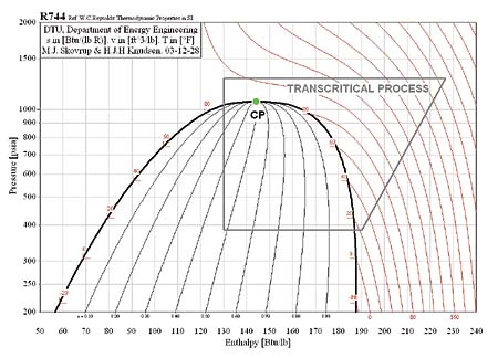
CO2 is not new to refrigeration. Its use began in the mid-nineteenth century and steadily increased, reaching a peak in the 1920s. Its use declined with the introduction of chlorofluorocarbons (CFCs) that operated at much lower pressures. Use of CO2 continued, but chiefly in cascade systems for industrial and process applications. Recently, strong interest has been shown in CO2 as a refrigerant by vending machine manufacturers. There are also possibilities for other light commercial refrigeration applications, as well as for residential air conditioning.The major challenges in CO2 refrigeration involve the relatively high working pressures. The supercritical portion of the transcritical cycle takes place above 1,067 psia. The phase diagram for CO2 is shown in Figure 1.

Pressure-enthalpy diagrams for a subcritical cycle with R-134a and a transcritical cycle with CO2 are shown in Figures 2 and 3. It is important to understand the differences between these two cycles.
Figure 2 is a pressure-enthalpy diagram for R-134a in a traditional vapor compression refrigeration cycle. Starting at the lower left of the figure and moving to the right, the bottom line represents the evaporation process. Refrigerant pressure (the y axis) remains constant in the evaporator, and heat gain during the evaporation process is represented by the in-creasing specific enthalpy (which can be interpreted as specific "energy content" of the refrigerant, measured along the x axis).
On the right side of the figure, the line slanting upward to the right as pressure rises sharply and steadily is the compression process, where we add power to the system to run the compressor.
In the top horizontal line of the figure, moving from right to left, the condensing process occurs. Here the heat absorbed during evaporation - and the heat added during compression - is rejected out of the system.
During the condensing process, the quality of the refrigerant changes until it is 100 percent liquid. A further cooling of the liquid often occurs so that the refrigerant is subcooled when leaving the condenser. There is no change in pressure or temperature during the phase change.
The final process in the cycle is expansion, represented by the drop in refrigerant pressure along the left side of the figure. The pressure drop occurs as the refrigerant passes through a metering device (expansion valve or capillary tube).
During the expansion process, refrigerant condition changes from subcooled liquid to a mixture of liquid and vapor. No heat or work is transferred to or from the refrigerant during this process, so the line representing the process is vertical. There is no change in specific enthalpy.
So in the cycle for R-134a, and for other subcritical refrigeration cycles, the four processes are evaporation, compression, condensation, and expansion. Note that the entire cycle takes place below the green dot at the critical point. Things are just a bit different in transcritical cycles.
Figure 3 represents a transcritical cycle with CO2. The cycle diagram looks the same; the only difference is that the heat rejection process occurs above the critical point. Unlike the subcritical condensing process, where temperature stays constant, temperature decreases during the entire transcritical heat rejection process. There is no condensation in a transcritical cycle, and we call the process gas cooling. In low ambient conditions, the process might occur below the critical point, and condensation, rather than gas cooling, would occur. This is the fundamental difference between subcritical and transcritical cycles.


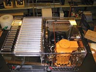
A Hermetic CO2 System
Figure 4 shows a simple CO2 transcritical system block diagram. There are two differences from the traditional system. One is the gas cooler that takes the place of the condenser, and the other is the expansion device.In subcritical applications, refrigerant is metered by a capillary tube or thermostatic expansion valve, the control strategy being to inject liquid into the evaporator and maintain a given superheat entering the compressor. The metering device is selected or designed to ensure that there is complete evaporation ahead of the compressor.
Superheat is maintained to ensure that evaporator efficiency is optimal, and that liquid refrigerant does not enter the compressor. Excessive superheat may lead to overheating of the compressor.
In systems where a thermostatic expansion valve is used rather than a capillary tube, superheat is maintained by placement of a sensing bulb at the outlet of the evaporator. The modulation of the valve is then controlled by the temperature transmitted to it from the bulb and the pressure at an internal or external equalization port.
A different control strategy is needed in transcritical cycles.
Transcritical Expansion Device
A system based on the transcritical CO2 cycle uses a high pressure expansion valve (HPEV). Rather than controlling refrigerant metering from the low-pressure side of the system, modulation control comes from the high side of the system. A mechanical HPEV will control refrigerant injection into the evaporator by opening and closing based on the increase or decrease in gas cooler pressure.In the HPEV, spring force is a closing force that acts on the top of a diaphragm. Increasing spring force throttles the valve, causing a backpressure in the gas cooler; the valve will not open until that back pressure, opposing spring force, increases to the point where it can overcome spring force and open the valve. The valve set point for the inlet pressure can be adjusted manually by compressing a spring in the valve.
Unlike a TEV, an HPEV does not control evaporator superheat. The HPEV injects refrigerant into the evaporator, but superheat is not directly controlled - instead it is indirectly regulated by system design.
The system charge, its distribution between the components, evaporator design, and the heat load, along with other external operating conditions, determines system superheat. By controlling the gas cooler pressure, the HPEV will indirectly influence system superheat, but the system must be designed so that liquid refrigerant in the evaporator outlet is not allowed to return to the compressor.
The HPEV was designed to control gas cooler pressure rather than suction line superheat as does a TEV. An HPEV, therefore, must withstand high-side CO2 pressures that can reach 1500 psia, at the same time accurately controlling gas cooler pressure. Slight changes in gas cooler pressure will have significant influence on the system cooling capacity and energy efficiency (COP).

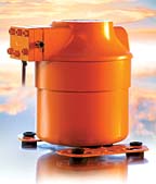
The Type TN Compressor For CO2
The function of the compressor in a transcritical application is the same as in a subcritical one. The compressor creates refrigerant flow, increasing discharge pressure and therefore raising refrigerant temperature to a level high enough that heat absorbed in the evaporator will be rejected in the condenser or gas cooler.Due principally to the higher CO2 working pressures, several challenges were presented during design of the TN compressor. Some of the major challenges were the shell construction, internal leakage across the piston, piston and bearing loading, and bearing lubrication, all due to the higher pressures. At the same time, to keep costs down, a simple design was chosen.
Outer shell construction had to be of increased robustness to handle the higher pressures. Piston rings had to be added to prevent internal cylinder leakage. The piston connecting rod bearing design was modified due to a smaller piston diameter and higher specific forces on the bearing.
The volumetric refrigeration capacity of CO2 is much higher than that of traditional refrigerants, allowing system designs with smaller volumes. This also holds true for other components. Smaller cylinder displacement still provides adequate system capacity.
CO2 systems operate at higher pressures, but the compression ratio is only 3 or 4 to 1. The lower compression ratio will give the compressor the capability to operate with less of a refrigerant re-expansion effect in the cylinder during operation.
Now that there are functional designs for compressors, heat exchangers, and high pressure expansion devices, the transcritical cycle with CO2 becomes a viable alternative for users seeking a solution that is acceptable worldwide. It is a natural refrigerant that will allow users to be identified as environmentally proactive. These facts will continue to fuel development of CO2 components and system designs.
Jeff Staub is manager of application engineering at Danfoss Inc., Baltimore. Bjarne Dindler Rasmussen is research engineer, Danfoss A/S, Nordborg, Denmark. Max Robinson is in Technical Communications at Danfoss Inc.
Publication date: 01/26/2004

Report Abusive Comment