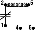
Potential or ‘voltage' starting relays are used with single-phase capacitor-start/capacitor-run motors, which need relatively high starting torque. Their main function is to assist in starting the motor. These starting relays consist of a high-resistance coil and a set of normally closed contacts. The coil is wired between terminals 2 and 5, with the contacts between terminal 1 and 2. Terminals 4 and 6 are used for capacitor and/or condenser fan connections and have no electrical significance to the starting relay itself (Figure 1). Terminals 4 and 6 are sometimes referred to as dummy terminals and are simply used for wire connections.
Fig. 2 shows how a potential starting relay is wired to a capacitor-start/capacitor-run compressor motor. Note that the relay coil is wired in parallel (across) the start winding. The normally closed contacts are wired in series with the start winding and the start capacitor.
OPERATION
When the power is applied through the cycling control, both the run and start windings are energized. The start and run capacitors provide the phase shift for starting torque because of their capacitance adding when wired in parallel.In fact, both capacitors are wired in series with the start winding and in parallel with the run winding. The run capacitor also limits the current that will pass through the start winding when the motor is running, since they are wired in series. The run capacitor also provides running torque when the motor is up and running.
The operation of the potential starting relay is based on the increase in back electromotive force (back EMF) or a bucking voltage that is generated across the start winding as the motor increases in speed. The large metal mass of the motor's rotor turning at high speeds with motor windings in close proximity has a voltage generating effect (Figure 3). This generated back EMF opposes line voltage and can be measured across the start winding or across the coil of the potential relay at terminals 2 and 5. The back EMF is usually a higher voltage than the line voltage and can be in the 400-V range. All motors have different magnitudes of back EMF.

The pickup voltage usually occurs when the motor has reached about 3/4 speed. The start winding is still in the back EMF circuit keeping the relay's coil energized while the motor is running at full speed.
When the cycling control opens, line voltage power is taken away from the motor. The motor's rotor decreases in speed, thus the back EMF generated across the start winding decreases in magnitude. The relay now sees a lowering back EMF and no longer can generate enough magnetism in its iron core to keep contacts 1 and 2 open.

John Tomczyk is a professor of HVACR at Ferris State University, Big Rapids, Mich. He can be reached by e-mail at tomczykj@tucker-usa.com.
Publication date: 07/03/2006

Report Abusive Comment