Bob is a service technician who is well trained and nationally certified. However, he sometimes suffers from the same confusion that all technicians occasionally do - the facts that he gathers may or may not point to the obvious cause of the problem or the best solution. But Bob has something that no one else has. He recalls his long-time HVACR mentor and imagines him accompanying him as "Btu Buddy," someone who reminds him to take time to stop and think before rushing to judgment, helping keep him on the right track, even with facts that are confusing.
In this installment of the Btu Buddy series, Bob is dispatched to a job at an insurance office where the office manager says the system is not cooling in some of the offices. It is a 20-ton cooling system with gas heat.
Bob goes in and talks to the manager who explains that all day yesterday, the offices on one end of the building were warm. The rest of the building seems normal. Bob goes to the equipment room where the air handler is located and discovers a set of building blueprints. The air handler sits in the middle of the ranch-style single-story building and there are two main trunk lines leaving the air handler, one to each end of the building.
Bob goes to the end of the building that is cooling correctly and takes an air temperature reading at several outlets. The temperature of the air leaving the registers is 55 to 57 degrees F. So he goes to the other end of the building and takes some more readings. It seems warm at this end. The supply registers read the same as the ones at the cool end of the building. However, the space temperature is 78 degrees F. It is warm for sure.
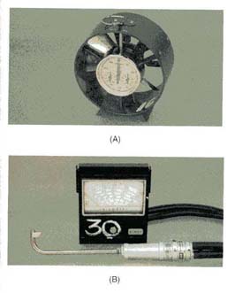
Bob then gets out his air velocity measuring instrument, his velometer (Figure 1). He takes some velocity readings in the cool end of the building and discovers the velocities to be averaging about 250 feet per minute (fpm). He then goes to the warm end of the building and finds the velocities to average about 100 fpm. There is definitely a reduced airflow problem, and Bob must determine what it could be.
Btu Buddy then arrives and asks, "What do you think the problem may be?"
Bob says, "I don't know."
Btu Buddy asks, "Are there any dampers in the air system that could be closed?"
Bob looks and says, "Yes, there are two dampers shown on the print, one on each main run of duct. They should be located overhead here in the equipment room."
Bob locates the dampers, but the damper handles show full flow in each direction to each run of duct, and the handles do not look as though they have been disturbed.
Btu Buddy suggests to Bob that he check the fan amperage. "If the fan motor is not pulling enough amperage, that could be an indication of reduced airflow."
Bob checks the amperage. It is a three-phase motor and the amperage is running 8 amps per phase. The full load rating on the motor is 12 amps.
Btu Buddy says, "The fan is not running under a load so that is another indication of reduced airflow. See on the motor disconnect switch where someone has marked 12 amps as the recorded running amps. It is a good idea to make those notes on the equipment so you have a reference point any time there is a question."
Btu Buddy remarks, "You have narrowed the problem down to an airflow problem. Now, we know that it must be in the supply duct because it seems to only affect one end of the building. What do you think you should do next?"
Bob scratches his head and says, "I can't imagine what it could be."
Btu Buddy asks, "How is the duct insulated?"
Bob responds, "With duct lining, on the inside. Could it have come loose and dropped down, and if so, where?"
"Well," comments Btu Buddy, "I don't see any weld spots on the outside of the duct where the duct liner tabs have been spot welded. It could be that the duct liner was fastened up with glue only. For some reason, the glue may have come loose."
Btu Buddy then says, "Start checking the air registers closest to the air handler and move down the duct. You may discover an airflow change and be able to better predict where the flow is reduced."

Tracking Down The Airflow Problem
Bob measures the air at the first two registers and it is averaging about 250 fpm. When he moves to the number three register, the airflow drops to about 100 fpm. He exclaims, "I think we have found the section of the duct where the restriction is, but now what can we do about it?"
Btu Buddy says, "There is only one thing you can do; you must cut an inspection hole in the duct and take a look. Cut the hole to a size where you can get your head up in the duct - make it good and square, with no sharp edges. It will have to be patched with sheet metal when you finish."
Bob gets his safety glasses and electric shears ready to cut the hole. He then lays out a square where he is going to cut the hole. Meanwhile, he calls the office and asks them to send out some sheet metal panels of the correct gauge of metal. He asks that the sheet metal foreman cut the panels and make a cross brake in them to give them strength and to punch holes around the perimeter for the screws to fasten the panels. He also asks for a gallon of mastic duct sealer to make the panels airtight.
Btu Buddy asks, "How are you going to fasten the duct liner back?"
Bob then tells the office to send some contact cement for fastening duct liner along with some sheet metal tabs that can be stuck to the inside of the duct for the duct liner. Figure 2 shows a sheet metal tab that sticks on the duct. The liner is pushed over the pin and a tab then pushed down over the pin.
Bob shuts the system down to stop all airflow while he is cutting. He then cuts out the inspection hole and looks in the duct. About 3 feet downstream, he finds the problem. Sure enough, the liner has come loose and about 2 feet of it has rolled up, blocking most of the airflow.

Bob then cuts another inspection hole where the liner is loose. He finds that the liner is in fact only glued. He then applies glue to the liner and the duct and lets it set for just a few minutes to allow the glue to become tacky. He has mounted several tabs in the same area to help hold the liner down. When the glue is ready to be contacted together, he rolls the liner back in place. He then puts the tabs on the pins to further hold the liner down.
Bob then runs some self-tapping metal screws into the holes in the panel covers to secure them. Once he has installed the two panel covers, he starts the system and measures the airflow at the registers in the warm side of the building and discovers an average of about 200 fpm. He goes to the cool side of the building and finds that the velocities average about 200 fpm. All of the air seems to be going to the right places now. A check of the fan amperage shows 12 amps.
Bob then liberally applies the mastic sealer to the edges of the newly installed panels. The system will be airtight where he worked on it.
Bob now says, "I thought that a restriction in a supply duct would cause high fan amperage."
Btu Buddy explains, "This is a common squirrel cage fan and the current draw is in proportion to the quantity of air that passes through the fan. The difference in the inlet and outlet pressure do not matter. (Figure 3 shows a fan under different types of restrictions.) It doesn't matter how the air is restricted, a reduced airflow will result in lower motor amperage. Because of this, the technician can measure airflow quantity using an ammeter. If the fan amperage is recorded at the time when maximum air is flowing, it can be used in the future for fan analysis."
Bob goes to the building manager and tells him what he found. Bob also schedules to come back and clean the evaporator and condenser coils when mild weather comes.
Btu Buddy says, "You did it again, you brought more business to your company and did a good job on the service call. You are really becoming a professional."
Bill Johnson has been active in the HVACR industry since the 1950s. He graduated in gas fuel technology and refrigeration from the Southern Technical Institute, a branch of Georgia Tech (now known as Southern Polytechnic Institute). He taught HVAC classes at Coosa Valley Vocational & Technical Institute for four years. He moved on to become service manager for Layne Trane, Charlotte, N.C. He taught for 15 years at Central Piedmont Community College, part of this time as program director. He had his own business for five years doing installation and service work. Now retired, he is the author of Practical Heating Technology and Practical Cooling Technology, and continues as a co-author of Refrigeration & Air Conditioning Technology, 5th Edition, all published by Delmar Publishers. For more information, he can be reached at 704-553-0087, 704-643-3928 (fax), or bmj@myexcel.com.
Publication date: 12/15/2003

Report Abusive Comment