They may be operated independently of each other, but their functions become interdependent. Because of this interdependent relationship, some close attention has to be given to the proper selection and matching of fan and damper. A fan inlet may be connected to other ductwork, either directly or via an inlet box, or the inlet may be unducted. This article considers only fans that have unducted inlets.
Air Movement
In a fan + damper system, the fan impeller imparts energy to air, moving it through the system, so it is necessary to consider exactly how air moves through a fan in order to understand the efficiency of energy usage in the air movement process and the factors that affect efficiency. As a fan impeller turns, a pressure difference is created between the inlet and the outlet of the fan.This applies to all types of fan impellers. Since air has no choice but to follow the path of least resistance, it does just that, and flows from outside the fan toward the low-pressure area at the fan inlet. Once the impeller blades have transferred some energy to the air, the air is shoved towards the fan discharge. So far this is simple enough, but air doesn’t move in only one or two dimensions; it moves in all three, and here is where things start to get interesting.
The rotating impeller blades create a series of low-pressure pockets towards which air moves as it enters the fan inlet. Since the pockets are moving in a circle, air tries to catch up to each pocket, but only part of the slower moving air can catch up with the faster impeller blades. The incoming air is then moving in a spiral from outside the fan through the inlet. This is known as inlet spin or inlet swirl. The rotational direction of inlet spin is always the same as that of the impeller.
Inlet spin is a natural phenomenon in the sense that it occurs when still air approaches the fan inlet; it is a result of the normal operation of the fan.

Working Together
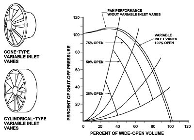
Variable inlet vanes (VIV) is one of several names given to a type of damper that is attached to, or assembled integrally with, the inlet of a fan. The VIV, as it is usually called, is round and has a central hub from which shafts extend outward to the main frame. Each shaft has a blade, and these blades are linked so that they all rotate together and in the same direction. VIVs, whether they are the add-on or an integral type (part of the fan inlet cone), have one feature in common: they open so that air passing through the fan inlet cone moves in the same rotational direction as that of the fan impeller. Arranging the operation of the inlet damper blades in this manner interferes the least with the natural flow path of air into the impeller while allowing full control of the volume flow.Control dampering of the flow of air at the fan inlet is usually preferable to control dampering at the fan outlet. From an energy standpoint, control at the inlet is a more efficient method. When the VIV is closed, air is blocked from entering the fan, but the impeller continues to create a negative pressure on any air that is available. When the damper is completely closed, the impeller exhausts all the air it is able to, and, in effect, creates a partial vacuum at the impeller inlet.
We know that nature is not fond of a vacuum, even when it is inside a fan. The static pressure at the fan discharge then forces air to leak around the impeller until a balance is reached between the ability of the fan to move air and pressurize the system, and the ability of the system to replace the air moved and pressurized by the fan impeller.
When this equilibrium is reached, the density of air in the fan impeller inlet is reduced somewhat, and it takes less power (and therefore less energy) to maintain the equilibrium. Except for a slight system effect loss due to having a device located directly at the fan inlet, VIV control is both effective and efficient throughout the operating range of the fan.
Making The Right Choice
A VIV control device should not be applied without considering the type of impeller with which it is expected to operate in conjunction. Just as there are impeller types that work better in certain applications than they do in others, certain impeller types are more suited to the use of a VIV than are others. A VIV is most effective in a centrifugal fan when matched with an impeller type that employs an inlet cone of some length. In this case, either an add-on or an integral VIV is suitable, though a specific application may dictate a preference for one style over the other.The centrifugal impeller types which are better suited to VIV applications are: airfoil (AF), backward-curved (BC), and backward-inclined (BI). Radial-bladed (RB) fans are also suited to the use of a VIV damper, but normally these applications are limited to the add-on style. The forward-curved (FC) impeller is not generally associated with VIV applications.
Axial impeller types that use VIV control are rare, and are limited to the add-on type of VIV. Most axial fan applications employ volume control methods that are either inherent in the fan design or are located at some distance away from the fan.
Volume flow control can also be achieved at the fan outlet, if necessary, and here as well, care must be exercised in matching the damper to the fan. At the fan outlet, damper performance is less dependent upon the impeller type and more so upon the geometric shape of the outlet and the pressure and turbulence of the discharge airstream. Airflow conditions at the outlet are just about opposite those at the inlet, where a VIV is intended to provide as little interference with the airflow as possible.
At the outlet, a volume control damper should be chosen on the basis of how much corrective effect it can apply to the turbulent airstream. Since volume control dampers are seldom if ever used with axial fans, only centrifugal fan applications will be considered here, and further limited to square/rectangular fan discharge openings.
There is a simple process of elimination involved in determining the characteristics of the volume control damper needed at a fan outlet. First, consider the opening into which the airstream discharges. If the next volume is large, such as a plenum, and there is no compelling reason to “help” the airflow, any style of louvered damper will probably serve the purpose. If the fan discharges into a duct system, an operating parallel-blade damper will divert airflow to one of the four sides of the discharge duct, adding further turbulence to the airstream.
A better choice would be an opposed-blade damper, which operates in such a manner as to allow air passing through it to move in guided, parallel streams. If this type of damper is selected, there remains one more choice: shall the blade shafts be parallel with or perpendicular to the axis of the fan shaft? Experience has shown that an opposed-blade damper installed with the blade shafts perpendicular to the axis of the fan shaft provides smoother operation and better control of airflow. This is the result we usually want.
Though the above choices may seem straightforward, it is best to remember that the circumstances of any specific application may dictate that another choice may be more appropriate. There are too many variables to list all the possibilities here. For more information, consult AMCA Publication 201-90, Fans and Systems, and AMCA Publication 502-89, Damper Application Manual.
This article was prepared by the Air Movement and Control Association International Inc. (AMCA). For more information, visit www.amca.org.
Publication date: 05/26/2003

Report Abusive Comment