Part One of this article provided some background on screw compressors, then discussed the various components and capacity control methods. Part Two discusses maintenance of the screw compressor.
Maintenance
To ensure a full operating life from a compressor, preventive maintenance is absolutely essential. Because the compressor is mounted on a unit, operating conditions of the unit play a major role in the life of the compressor. Below is a list of preventive maintenance items dealing both with the compressor and the unit. First and foremost, always follow the manufacturer’s recommended maintenance schedule. However, the following recommendations can be applied to most systems.Operating Logs
Recording the operating conditions every four hours or at least once per shift permits those responsible for the maintenance and servicing of the equipment to be constantly familiar with the operation of the system. Any deviation from the normal operating conditions is easily recognized and immediate steps can be made to correct the problem. A few typical areas to look for would be high or low discharge temperature, high or low oil temperature, low oil pressure, and high full load amp percentage.Discharge Temperature
Lower than normal discharge temperatures could indicate liquid refrigerant carry-over or excessive liquid injection feed.Higher than normal discharge temperatures could indicate an incorrect Vi (volume ratio) position, insufficient main oil supply, excessive suction line superheat, or an increase in the rotor end clearance.
Oil Temperature
Excessively high oil temperature can adversely affect the oil’s ability to supply proper lubrication.If the oil temperature is too low, refrigerant may become entrained in the oil supply and enter into the bearing cavities.
An increase in full load amps while maintaining the same operating conditions could indicate a faulty bearing.
Rotor Thrust Measurement
Measuring the axial movement of the rotor can help determine the condition of the thrust bearing. By moving the rotor axially back and forth, and comparing that measurement with the “as built” measurement, excessive thrust bearing movement can be detected. Obviously, the drive rotor is easy to measure as it protrudes from the compressor; however, access to the non-drive rotor will require some disassembly of the compressor.For compressors with anti-friction roller bearings for radial loads, clearance measurements can only be taken with a feeler gauge between the inner race and the top roller element. Do not pry the rotor up and down. Excessive radial movement of the rotor shaft could result in damage to the bearings.
Oil Analysis
The use of the correct oil in a compressor is essential for long-term operation. Ensuring that the oil quality is in line with the manufacturer’s recommendations is equally important. Conducting oil analyses in scheduled intervals allows the operator to know the condition of the oil and when it is time to change the oil. An oil analysis should look for viscosity, moisture, wear metals, particle count, and on certain refrigerants, total acid number. Consult the compressor manufacturer for testing lab recommendations. It is important to have a testing laboratory that is knowledgeable about refrigeration oils.Vibration Analysis
Vibration analysis is a highly accurate and effective method to monitor the condition of anti-friction bearings. A quality vibration program, monitoring compressors with anti-friction bearings, can give advance warning of bearing defects long before a complete failure. Vibration analysis can also eliminate the need for periodic teardown inspections that are typically based on hours. It is important that the person taking the readings is familiar with the bearings and the operation of the compressor.Being Familiar With The Compressor
Not all companies can financially afford the benefits of oil or vibration analysis programs. In this case, a trained operator can become familiar with their compressor to the point that changes in sound levels and pitches can alert them to a problem.Remember that preventive maintenance is proactive and can save both time and money.
Servicing
Minor repair:This is usually defined as work performed on the compressor while it’s still mounted on the unit. Typical minor repair items would consist of replacing the slide valve and slide stop potentiometers, slide valve piston seal ring, and miscellaneous O-rings. High on the list of minor repairs would be replacing the shaft seal. Compressor manufacturers attempt to install reliable and durable shaft seals; however, the most durable shaft seal will have to be replaced eventually. A shaft seal, like bearings, is designed with a particular compressor and application in mind. It is important to consult the compressor manufacturer for the correct shaft seal.Major repair categories: Major repair to compressors can usually be broken down into three categories. The first would be replacing bearings, O-rings, and fasteners. This type of repair is often associated with hours of operation rather than a known problem. Some manufacturers recommend this type of repair as a scheduled maintenance item. However, since the onset of vibration analysis, many end users now rely on vibration measurements to predict the need for rebuilding rather then operating hours. As discussed earlier, vibration analysis can often detect a problem before it is audible to the human ear.
The second category would be bearings, O-rings, and a few internal components. Again, this could be based on hours of operation and vibration readings as well as audible noise or compressor performance. Replaceable items could be balance pistons, slide valve, and slide stop.
The third category would include the first two groups as well as additional major components. Items such as rotors and major housings would be required as a result of a compressor failure. Compressors falling into this category will need to be evaluated to determine if rebuilding is a more financially advantageous decision than purchasing a replacement compressor.
Dismantling
Discussion on compressor dismantling is somewhat difficult due to the scores of different compressor designs on the market. No matter which design is being dismantled, a few basic steps and procedures should be followed.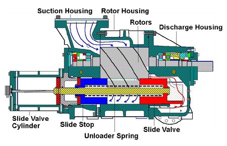
Assembly
Other critical items are bearings. Bearings are designed to handle specific loads, speeds, and conditions. Although the bearing manufacturer has a generic identification on their bearings, the identification may not always specify the exact bearing design. An example of this may be that the bearing clearance is not specified on the bearing code. As mentioned previously, it is strongly recommended to use the manufacturer’s designed shaft seal.
Once the correct seal is obtained, a few basic pre-installation techniques are recommended.
1. Ensure all compressor components are cleaned and ready for re-installation before removing the shaft seal from its package.
2. Once the seal is removed from the package, care must be taken to avoid contamination.
3. Never attempt to wipe the seal faces with anything other than a clean alcohol swab. Seal faces are lapped to two to three helium light bands. One helium light band is 11.6 millionths of an inch. Rubbing the faces with some other cloth may result in scratching the face.
4. The majority of shaft seals require coating the surfaces with oil prior to installation. Never wipe on the oil with a cloth or brush as both may either scratch the carbon or leave contaminants. The seal can be lubricated by either dipping the seal in clean refrigeration oil or by using a spray bottle.
5. Never use grease or products such as STP for either installation or lubrication. These products have a higher viscosity than refrigeration oil and may cause premature failure due to sludge formation.
Most shaft seals have an allowable oil leak rate; check with the manufacturer for the maximum allowable rate. Below is a list of possible causes for excessive shaft seal leakage.
Failure Analysis
Another important aspect in compressor rebuilding is to determine the cause of failure by analyzing the failed components. The most common mistake during a teardown evaluation is concentrating on the damage that occurred rather than what caused the damage. To get a better understanding of what to look for, the following is a list of possible failure modes.
Perhaps the leading cause for compressor failures can be attributed to lubrication-related problems. Poor lubrication will cause the bearings to fail. Although it could be described as a bearing failure, it would actually be a lubrication failure. Partial lists of items that contribute to a lubrication failure are listed below:
1. Using the wrong type of oil.
2. Contaminants such as moisture, particles, or liquid refrigerant.
3. Mixing different types of oils.
Again, it has to be determined what caused the bearing to fail in order to determine what caused the compressor to fail. To determine a bearing failure, it is best to evaluate all the bearings. A partial list of bearing failure modes is shown below.
1. Failure due to defective bearing seats on shaft and in housings: For the bearing to achieve its life expectancy, it’s essential that the shaft and the housing be geometrically true with the bearing.
2. Misalignment: Misalignment can occur between the compressor and motor or it can occur if the inner ring is seated against a shaft shoulder that is not square.
3. Faulty mounting practice: Failures under this item occur from abuse or neglect of the bearing before and during mounting. Besides mechanical damage as a result of abuse, allowing the bearing to become contaminated will result in a premature failure.
4. Damage due to improper fit: This occurs when the wrong bearing design is used. This typically occurs when deviating from the manufacturer’s specified bearing.
5. Inadequate or unsuitable lubrication: This occurs when using the wrong specification of oil or poor quality oil.
6. Vibration: A unit that is vibrating excessively during operation will result in premature bearing failures. Another type of vibration-related failure is called false brinelling. False brinelling occurs when the compressor is off for an extended period of time without the rotor shafts being rotated while a nearby machine is running. Micro-motion occurs between the rolling elements and inner raceway that will eventually cause the raceway to fatigue at the contact point.
7. Passage of electric current through the bearing: In certain electrical machining applications, there is the possibility that an electrical current will pass through the bearing. A few possible causes would be stray magnetic fields or through a welding operation on some part of the machinery with the ground attached so that the circuit is required to pass through the bearings.
8. Old age: Bearings are chosen during the initial design of a compressor based on “L10” life. L10 life is defined as the operating hours that 90 percent of a bearing population would be expected to meet or exceed before any wear surface develops a 1 mm square fatigue spall. The median life is approximately five times the L10 life. Good quality lubricant and a clean operating system can give operating service life well beyond the calculated L10 life. However, if compressors run long enough, the bearings would eventually be expected to fail from fatigue, or old age.
Bearing Installation And Mounting
To ensure that the correct bearings are being installed, it is recommended that bearings be obtained from the compressor manufacturer.Anti-friction bearings typically come in two mounting types, loose fit and interference fit. Loose fit bearings are designed to slide into the bore or over the shaft without resistance. Interference fit bearings require some assistance for installation.
Four different mounting methods are used for anti-friction bearings, including cold mounting, hot mounting, oil injection, and slip fit. The most commonly used methods are cold mounting, hot mounting, and slip fit.
Cold mounting takes place when a bearing is frozen prior to installation. Freezing shrinks the bearing allowing it to be easily installed in the bore. Once the temperature of the bearing increases, it fits snugly in the bore. Cold mounting is also used to describe a bearing that is mechanically forced into position. Hot mounting is used for bearings that require interference fit. A typical application would involve the inner race of an anti-friction roller bearing. Heating expands the race allowing it to be easily slid into position. As the race cools it adheres to the rotor shaft. Slip fit bearings simply slide into place with normal hand force.
Yoder is a service technician with York Refrigeration/Frick in Waynesboro, Pa. For more information, visit www.yorkref.com.
Publication date: 03/10/2003

Report Abusive Comment