The purpose of this article is to cover the higher percentage problems and repair procedures of thermostatic expansion valves (TEVs or TXVs) in supermarket applications.
A brief review of basic TEV operation is in order. The diaphragm is the actuating member of the TEV. There are three fundamental pressures acting on it: Sensing bulb pressure P1, equalizer pressure P2, and the equivalent spring pressure P3.
The sensing bulb pressure is a function of temperature and acts on the top of the diaphragm causing the TEV to move in an opening direction. The equalizer and spring pressure act together underneath the diaphragm causing the valve to move in a closed position.
Under normal operation (disregarding the pressure differential required across the diaphragm to move it), sensing bulb pressure equals equalizer pressure plus spring pressure, i.e., P1 = P2 + P3. It is important to note that spring pressure is essentially constant once the valve is set.
As a result, the TEV is actually controlling the difference between the bulb and the equalizer pressures, which is the amount of the spring pressure. The spring pressure represents the superheat the valve is controlling at the bulb location.
Now with TEV basics aside, let's review some of the higher percentage TEV problems when servicing a supermarket. The subject valves had previously been operating at the correct superheat setting.
The Valve Will Not Feed Enough Refrigerant
1. Check the TEV adjustment:The factory setting of a Sporlan TEV, for example, is close to center stem. Count the total number of turns front seat to back seat, then front seat the adjustment stem to 50 percent of the total turns counted.Turn the adjusting stem counterclockwise in increments of one-half to one full turn every 15 minutes until the correct superheat is reached.
2. Check the sensing bulb location: The sensing bulb should be securely fastened to a clean, straight section of the suction line. The bulb should not be influenced by ambient air temperature. The bulb should be attached to a horizontal suction line at the evaporator outlet.
If the bulb cannot be located in this manner, it may be located on a descending vertical line only. On suction lines 7/8 inch and larger, it should be installed at 4 or 8 o'clock on the side of the horizontal line. On smaller lines the bulb may be mounted at any point around the circumference except the bottom of the line where oil may influence the sensitivity.
On multiple evaporators, the piping should be arranged so that the flow from any one valve cannot affect the sensing bulb of another. The equalizer connection should be made at a point several inches downstream of the bulb.
Verify the sensing bulb is correctly installed.
Note: This check is also valid when the TEV is flooding the evaporator.
3. Check for moisture: Water or a mixture of water and oil frozen in the valve port (or working parts of the valve) prevent proper operation. Since the valve is the first cold spot in the system, moisture will freeze restricting flow.
The fact that the system has not been opened for years does not eliminate the potential for this problem. Elevating the temperature of a liquid line drier (already at maximum water retention) beyond its normal operating temperature can cause it to release moisture into the system.
Liquid lines increase in temperature during a slow refrigerant leak, dirty condenser coil, failed condenser fan motor, etc.
Pour a cup of hot water on the valve body to melt the suspected internal ice formation. A telltale audible surge in refrigerant flow will indicate system moisture. Install a new filter drier.
Note: This check is also valid when the TEV is flooding the evaporator; the valve may freeze in a "too open" position.
4. Check for contaminants in the valve body: Look for restrictive dirt or foreign material such as copper oxide scale, metal chips, oil breakdown, sludge, etc. Conventional strainers allow some types of these materials through, ultimately obstructing the port of the TEV.
Pump the system down, disassemble and clean the TEV. Install a filter drier directly ahead of the TEV if additional contaminants are suspected between the main liquid line filter and the restricted TEV. If no contaminants are found, install a sight glass ahead of the TEV and go to step 5.
Note: This check is also valid when the TEV is flooding the evaporator; the foreign material may prevent the valve from closing.
5. Check for a solid liquid column to the TEV: Install a liquid line sight glass directly ahead of the TEV during step 4 while the system is pumped down. If flash gas is present, check for a liquid line restriction or pressure drop.
Correct the pressure drop as required. If the pressure drop is because of the length of the piping run or liquid lift, install a heat exchanger to subcool the refrigerant to the required temperature for elimination of the flash gas.
6. Check design pressure drop for required TEV capacity: The capacity of the TEV is a variable dependent on the pressure differential across the valve. Greater pressure drop across the TEV equals greater TEV capacity.
Remove the source of the pressure loss on the inlet, or pressure increase at the outlet. If the inlet pressure to the valve is due to low condensing pressure, in-stall the appropriate head pressure controls. Installing a larger TEV is the last resort.
7. Check for element charge migration: Pressure-limiting type element charges have a limited volume of constituents. The bulb temperature must be lower than the element or the bulb constituents will migrate into the element causing the valve to throttle and/or close.
Warm the element with a heat gun, returning the superheat to normal. Relocate the valve body to a location with a higher temperature than the sensing bulb.
TEV Continuously Or Cyclically Floods Evaporator
A TEV is a modulating type valve with the ability to modulate the refrigerant flow rate much lower than its full-load design rating. The more oversized the TEV, the larger the valve superheat swings. The superheat swing references the number of degrees change from high to low at the evaporator outlet as the TEV modulates. The superheat swings are also referred to as "hunting."A conventional nonbalanced port TEV can modulate down to about 30 percent of its maximum loading. TEV hunting at this minimal percent is large enough that liquid refrigerant can spill past the sensing bulb before the valve throttles.
A balanced port TEV can modulate down to approximately 25 percent of its maximum load rating before spillover occurs.
Note: Increased pressure drop or decreased entering liquid temperature beyond design conditions increases the TEV's capacity.
8. Check the TEV adjustment: The factory setting of a Sporlan TEV, again, is close to center stem. Count the total number of turns from front seat to back seat, then front seat the adjustment stem 50 percent of the total turns counted.
Turn the adjusting stem clockwise in increments of one-half to one full turn every 15 minutes until the correct superheat is reached.
9. Check for a solid liquid column to the TEV: The TEV adjustment stem may be opened far enough to offset less than a solid column of liquid in some applications. Should the condensing temperature drop, resulting in subcooled refrigerant (a solid head of refrigerant), the TEV may flood.
A lighter evaporator load may also result in a solid head of refrigerant to the TEV, leading to a flooded evaporator condition that did not formerly exist.
Install a liquid line sight glass directly ahead of the TEV and verify a solid head of refrigerant during the adjustment procedure.
10. Time study the flooding cycles: A TEV with a severe hunt will go to 0 degrees of superheat before the valve throttles closed. It may take up to several minutes for the liquid refrigerant in the flooded evaporator to boil off (exhibiting zero degrees superheat). The evaporator superheat may then conversely rise 10 degrees or more for an additional minute or two before starting the cycle over.
A TEV that is exhibiting this type of cyclical flooding condition should slowly be adjusted open. Not only will the higher superheat value get lower, the 0 degrees at the bottom of the TEV swing will increase to a superheated value. Reducing the adjustment spring pressure results in a higher volume, less erratic evaporator feed, in most applications.
11. Check the evaporator for air-side heat loading: The number of air turns in a walk-in cooler or feet per minute airflow in a refrigerated fixture should not be reduced. A loss of air movement because of dirt, ice, missing sheet metal panels, or incorrect product load levels results in a loss of heat transfer. The TEV may hunt and flood if loaded too lightly.
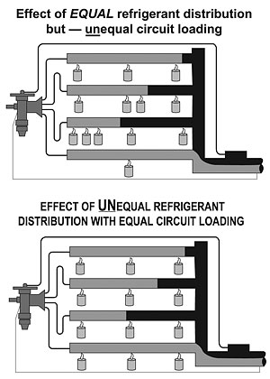
12. Check the evaporator for unequal circuit loading: Multi-circuit evaporators and parallel evaporators connected to a single refrigerant distributor must receive an equal percentage of the total load.
When each circuit is not subjected to the same heat load, the lightly loaded circuits will allow liquid refrigerant or low temperature vapor to enter the suction line and throttle the TEV. This will cause normally loaded circuits to be deprived of their share of the refrigerant (Figure 1).
The net result is a loss of refrigerated evaporator surface and a potentially oversized TEV. Check the temperature of the suction outlets of each distributor circuit before the suction header. Unequal temperatures at these locations are the result of unequal loading.
Check with the equipment manufacturer for the correct distributor and nozzle assembly if poor distribution is diagnosed.
Reprinted with permission from Sporlan Valve Company Form 10-143. For more information, contact Sporlan at 206 Lange Drive, Washington, MO 63090; 636-239-1111; 636-239-9130 (fax); www.sporlan.com.
Publication date: 09/27/2004

Report Abusive Comment