In this edition of the Btu Buddy series, Bob is scheduled to help finish a job that a new construction crew installed. The installers left the gas line and liquid line on a heat pump at the jobsite turned up all weekend and it rained in the tubing. The foreman noticed it and asked for the service department to finish the job.
Bob arrives at the job and sees right away what the problem is. Sure enough, the new construction department has made a mess of this one. The installation crew had run the gas and liquid lines out to the outdoor unit and just turned them up on the ends, with every intention of plugging them before they went home for the weekend, but they didn’t. There were no gutters on the house and water from the roof just ran in the lines. The lines had a fairly long horizontal run and all lines were standing full of water. This would be the end of these systems if they were just connected to the outdoor units and started up. The foreman had made a good call getting the service department involved at this time.
Bob turned the lines down to drain as much water out as he could and was standing there wondering what to do next when Btu Buddy appears and says, “Why don’t you solder 1/4-inch connectors in the liquid lines first and purge the lines with nitrogen to push as much water as you can through the system and out the gas lines.”
“Why connect to the liquid line first?” asks Bob.
“Well, the bulk of the freestanding water will be in the large line, the gas line. This way, you can push most of the water out toward the large line. You could actually go up and remove the metering device and really get the best velocity through the line, but it is brazed in the system,” says Btu Buddy.
Bob does as Btu Buddy suggests and prepares to purge the system with nitrogen. He finds that the upstairs system has very little water in it. When he turns the pressure on to the downstairs system, water just keeps blowing out. The indoor coil for this system has a lot of water in it. The upstairs unit only had water in the piping.
Btu Buddy says, “Bob, you need to use every advantage you have to evacuate this system to a very deep vacuum. This is a low temperature system in the winter. If there is a drop of moisture circulating in the system, it will eventually get to the metering device in the winter when the system is operating below freezing and stop the entire system.”
Bob asks, “Will a single drop of water really stop the system from functioning?”
“Absolutely,” says Btu Buddy. “The industry has always said that a good low temperature refrigeration technician makes a great air conditioning technician. The reason is that refrigeration technicians really understand moisture in a system. It just cannot happen. Moisture can actually circulate in an air conditioning system because it never operates below freezing, but it cannot be tolerated in a low temperature system. You should never allow moisture in an air conditioning system for other reasons besides freezing. Moisture will combine with the refrigerant and heat in the compressor and make acid. There is not a lot of acid. But it is enough to cause electroplating in the compressor.
“Remember, the elements that must be present for electroplating are electricity, acid, and dissimilar metals. The acid is formed from the moisture, there is electricity from electrical supply in the hermetic compressor, and there is copper and steel in the system. The electroplating normally plates from the soft metal to the hard metal, so the copper is plated to the steel crankshaft and wrist pins. This closes the tolerance between the shaft and the rod and causes it to bind. This is one reason why a compressor may not start.”
Btu Buddy continues, “Most of what you remove from a system when you evacuate it is nitrogen from pressurizing the system, or atmosphere which may have small amounts of moisture because the system has been open. These are very easy to remove.”
Bob asks, “How much water do you think is still in the downstairs system?”
Btu Buddy says, “It is hard to tell. You really can’t get much velocity through the pipes with the metering device still in the system, but we can use some tricks and get it cleaned up.”
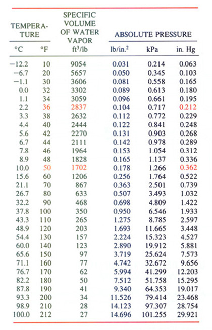
Btu Buddy explains, “If there is freestanding water in the system, this water must be boiled to a vapor before it can be removed. Water actually creates large volumes of vapor. One pound of water vapor will generate about 867 cubic feet of vapor when boiled (evaporated) at 70 degrees F. If a large vacuum pump is used to dehydrate a system after a water leak, it may boil the water at an even lower temperature, such as 40 degrees F where it would create 2,444 cubic feet of vapor (Figure 1). If the moisture is boiled too fast, it can actually turn the moisture to ice and it is really hard to remove. The typical technician working on residential equipment may not ever have to evacuate a flooded system. When an evacuation needs to be accomplished where large volumes of vapor have to be removed, the correct procedures must be used.”

Quick Evacuation
There are two key elements for a quick evacuation, notes Btu Buddy, whether a large amount of vapor is present or a small volume of vapor needs to be removed in a hurry:1. Large-bore leak-free tubing; and
2. The correct size and type of vacuum pump.
When a large vacuum pump is used and small gauge lines with possible leaks, such as 1/4-inch typical gauge line hoses with crimped fittings, O-ring seals, and Schrader valve connectors, you can expect it to be slow with possibilities of leaks.
“Bob, you have a special gauge manifold that can be used with your vacuum pump for quick evacuation,” Btu Buddy says. “This manifold would speed up the evacuation, and time is money saved for the customer. This gauge manifold is the four-line manifold that includes both a refrigerant cylinder connection and a vacuum pump connection (Figure 2). The vacuum line is 3/8 inch instead of the typical 1/4 inch.
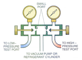
To speed evacuation, remove the valve depressors at the end of the gauge lines, says Btu Buddy. “Remove the valve stems from the Schrader valves on the liquid and suction line. Evacuate the system and when the evacuation is complete, pressure the system back to 0 psig with refrigerant and replace the valve stems. Place a valve stem depressor valve (Figure 5) at the end of each gage line, reconnect the gauge manifold to the system, and charge it. This will give a quick evacuation to a very deep vacuum.”
The four-line manifold also prevents sucking air into the manifold while disconnecting from the vacuum pump to connect to the refrigerant cylinder (Figure 6). “There is no way to disconnect a typical manifold from a vacuum pump without pulling air into the valve section,” remarks Btu Buddy. “Once that air is in there, it can’t be purged from the manifold while connected to the system that is under a vacuum. This air in the system only amounts to a very small amount, but the manufacturer calls for ‘no air,’ not a little bit.”

Btu Buddy says, “Well, get the manifold and vacuum pump and let’s use it to its maximum benefit.”
Bob gets the tools and solders another 1/4-inch fitting into the gas line on each heat pump line set and starts the vacuum pump on the upstairs unit. As mentioned above, Bob had removed the valve stem depressors from the gauge manifold lines so the lines had their full 1/4-inch bore without any restrictions.
Btu Buddy suggests, “Let’s leave the line set capped at atmospheric pressure when we have finished dehydrating it. The construction crew can then finish their job just as it should have been and you can move on to more service calls.”
Bob says, “That sounds good to me.”
The vacuum pump runs for about 15 minutes and the micron gauge goes down to 5,000 microns (the same as 5 millimeters). Btu Buddy then suggests that Bob shut off the vacuum pump and look for a rise in pressure. The pressure goes up a little and stops. Btu Buddy then suggests that Bob allow some nitrogen into the lines to help blow out any moisture in the system. Bob allows nitrogen in the system until the pressure is about 10 inches of vacuum on the manifold vacuum gauge and starts the pump again. The system quickly pulls down to 5,000 microns and keeps on going down.

Bob then connects the vacuum pump to the second system, the one that seems to have more water in it. The vacuum pump runs for about 30 minutes and only pulls down to 29 inches on the compound gauge and seems to stall. The micron gage was not even reading because it’s scale starts at about 5,000 microns. The pump continues to run. Btu Buddy comments, “The vacuum pump is working; you can hear the tone change. Valve it off and listen to what it does.”

About an hour later, Bob notices the oil level is rising in the vacuum pump. It is also turning white or milky colored. “What is going on?” Bob asks Btu Buddy.
“This is normal; you are pulling water from the system. This water is displacing the oil in the vacuum pump. It is time to change it,” says Btu Buddy.
Bob valves the vacuum pump off and drains the oil. He adds new oil and starts the pump again.
Btu Buddy says, “If you do not change the oil periodically under these circumstances, the water will completely displace the oil and ruin the pump. You must take very good care of the vacuum pump. You will have to change the oil again. Actually, when the system begins to pull down, you will have to change it two or three times to reach the desired vacuum. This pump has a gas ballast that is supposed to prevent moisture from entering the pump crankcase, but there is too much water in this system to stop all of it. After you are through with this system, you will need to change the oil several times to clean the pump up for the next job. Keep saving the old oil and we will dispose of it in the proper way. You are lucky this pump only takes a few ounces of oil, unlike the pumps of the past where you would be collecting a gallon or more of used oil from a job like this.”
About an hour later, the system pressure begins to fall and register on the micron gauge. The oil in the vacuum pump was milky again and rising in the crankcase. Btu Buddy advised, “It is time to change the oil until the vacuum pump is clean.”
Bob changes the oil until the vacuum pump pulls the vacuum gauge down to 100 microns. This is accomplished with the valve between the micron gauge and the system. Btu Buddy explains, “The vacuum pump is clean and ready to go for the deep vacuum.”
Bob connects the pump and starts it. The pressure keeps falling until the system is down to 300 microns. Bob adds nitrogen to the system until the pressure is about 10 psig, removes the gauges, and caps the lines for the construction crew.
Btu Buddy advises, “Change the oil in the vacuum pump again while it is hot. The residual oil and any moisture will drain from it completely while it is hot.”
Bob changes the oil and puts the vacuum pump back in the truck compartment.
As they were leaving the job, Btu Buddy says, “You did a good job with this system. It is as dry as the manufacturer sent it out. This system will provide long service life. You have the best of tools provided by your company and that allows you to do a professional job.”
Bill Johnson has been active in the HVACR industry since the 1950s. He graduated in gas fuel technology and refrigeration from the Southern Technical Institute, a branch of Georgia Tech (now known as Southern Polytechnic Institute). He taught HVAC classes at Coosa Valley Vocational & Technical Institute for four years. He moved on to become service manager for Layne Trane, Charlotte, N.C. He taught for 15 years at Central Piedmont Community College, part of this time as program director. He had his own business for five years doing installation and service work. Now retired, he is the author of Practical Heating Technology and Practical Cooling Technology, and continues as a co-author of Refrigeration & Air Conditioning Technology, 5th Edition, all published by Delmar Publishers. For more information, he can be reached at 704-553-0087, 704-643-3928 (fax), or bmj@myexcel.com.
Publication date: 09/22/2003

Report Abusive Comment