Carbon dioxide (CO2) is not new to refrigeration systems. Alexander Twining proposed using CO2 as a refrigerant in a British patent granted him in 1850. Thaddeus S.C. Lowe, perhaps best known for his experimentation with CO2 military balloons, designed an ice machine using CO2 in 1867. Lowe also developed a machine for marine transportation of frozen meat.
The use of CO2 became more and more prevalent, peaking in the period from 1920 to 1940, and waning thereafter due to technical problems with the high pressures and leaks. Then DuPont began successfully marketing CFC refrigerants.
In the 1990s there was renewed focus on the advantages of CO2. Concerns with ODP (ozone depletion potential) and GWP (global warming potential) began to result in restrictions on the use of CFCs and HFCs and in restrictive charge limits for large ammonia systems.

CO2 As A Refrigerant
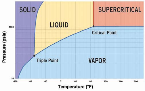
CO2 is one of the so-called "natural" refrigerants, a group that includes ammonia, hydrocarbons such as propane and butane, and water. Each has its respective disadvantages limiting its application possibilities. In comparison, CO2 is nontoxic and nonflammable, but has a dual environmental role. Although CO2 is necessary for all life on earth, it is also a greenhouse gas that can bring about environmental changes if its atmospheric concentration changes.The pressure-enthalpy diagram for CO2 is shown in Figure 1. The phase diagram for CO2 is shown in Figure 2.

It may seem that the thermodynamic properties of CO2 are similar to those of other common refrigerants, but there are some noteworthy differences. The triple point for CO2 is much higher than that of any other common refrigerant (see Table 1). In the pressure-enthalpy diagram (Figure 1), the triple point is actually a line at a pressure of 75.1 psia and a temperature of -133.9 degrees F. At the triple point, CO2 vapor, liquid, and solid are in equilibrium.
The critical pressure of CO2 is 1,067 psia, and the critical temperature is 88 degrees. Above the critical point, in the supercritical phase, CO2 has properties that are almost similar to those of a high-density vapor.
The high-saturated pressure at ambient temperature is often the first barrier to consider when proposing CO2 as a refrigerant. At 68 degrees, the saturated pressure is 829.6 psia. CO2 can be used in various system configurations, depending on application requirements. The configuration is very much dependent upon the application.
A single-stage, subcritical CO2 system is simple but it has the disadvantages of high pressure and a limited temperature range.
Transcritical (supercritical) CO2 systems are interesting for specific smaller applications - less than 3 TR - where the high system pressures can be safely engineered at reasonable cost. The automobile industry is concluding a number of air-conditioning research projects and is preparing for introduction of the technology in few years. Commercial applications are being investigated, and the components needed are currently being developed, based on many years of research. Focus is presently on hot water heat pumps and commercial sales equipment.
Hybrid systems are the most common designs used in industrial refrigeration because the pressure can be limited to a level where the requirements for components like compressors, controls, and valves differ only slightly from those of traditional industrial refrigeration plants.
CO2 systems can be designed in different configurations: direct expansion (DX), pump circulating, secondary brine, and combinations of these. Descriptions of some common industrial systems follow.
CO2 In Industrial Systems
Figure 3 shows a low-temperature refrigeration system (-40 degrees) that uses CO2 as a phase-change refrigerant in a cascade system with ammonia on the high-pressure side.
The CO2 system is a pump circulating system where liquid CO2 is pumped from the receiver to the evaporator, where it is partly evaporated before it returns to the receiver. The evaporated CO2 is compressed in a CO2 compressor, and condensed in the CO2-NH3 heat exchanger. The heat exchanger acts as an evaporator in the NH3 system.
Figure 4 shows the same system as in Figure 3, but includes a CO2 hot gas defrosting system. Figure 5 shows a low temperature refrigeration system (-40 degrees) using CO2 as a brine system with ammonia on the high-pressure side.


The CO2 system is a pump circulating system, where the liquid CO2 is pumped from the receiver to the evaporator. Here it is partly evaporated before it returns to the receiver. The evaporated CO2 is then condensed in the CO2/NH3 heat exchanger. The heat exchanger acts as an evaporator in the NH3 system.
Figure 6 shows a mixed configuration with both flooded and DX subsystems. Mixed systems are found in applications like supermarkets, where two temperature levels are required.

Design Pressure
There are two important factors to take into consideration when determining the design pressure of a CO2 system: high off-cycle pressure and defrost pressure when hot gas defrost is used.Off-cycle pressure can be very high. This challenge can be met in several ways:
Defrosting pressure during hot gas defrosting must also be taken into consideration.
No single defrost method predominates. Natural, water, electrical and CO2 hot gas defrosting are all used, depending on the system and on the availability of suitable compressors and other components.
Of the various defrost strategies, CO2 hot gas is the most efficient, especially at low temperatures, but it also has the highest pressure demand. With a design pressure of Psat = 725 bar, it is possible to reach a defrosting temperature of 48 degrees to 50 degrees. The saturated pressure at 48 degrees is 636.7 psig. By adding 10 percent for the safety valves and approximately 5 percent for pressure peaks, the requirement is for pressure Psat of approximately 725 psig.
Efficiency
CO2/NH3 cascade systems re-quire a heat exchanger. Introducing exchangers creates a loss in system efficiency due to the necessity of having a temperature differential between the fluids. But compressors running with CO2 have greater efficiency and heat transfer is greater. The overall efficiency, therefore, of a CO2/NH3 cascade system is not lower when compared to that of a traditional NH3 system.Next Month: In the second article in this series on CO2 as a refrigerant, the authors will discuss system compatibility considerations including oils, water effects, leak potential, and safety with regard to CO2 refrigeration systems.
Vestergaard is R&D manager for Danfoss Industrial Refrigeration; Robinson is in technical communications in the Air-Conditioning & Refrigeration Division, Danfoss Inc.
Publication date: 10/06/2003

Report Abusive Comment