In this installment of the Btu Buddy series, Bob and Btu Buddy meet at the local diner for lunch.
After their meal, Btu Buddy says, "Now that we've had lunch, let's have a cup of coffee and talk about electric heat and the components that operate it."
Bob asks, "Where do we start?"
Btu Buddy says, "The first thing that you must realize is there is a lot energy being dissipated with electric heat. The reason for this energy release at the heaters, instead of at the wires entering, is management of electrical resistance in the electric circuit."
Bob asks, "What do you mean by management of resistance?"
"Well," Btu Buddy says, "have you ever wondered why the electric heat element gets hot and the wires leading up to it don't?"
Bob says, "I don't think that I have ever thought of that, but you are right. The heat is concentrated at the heating element."
Btu Buddy explains, "The reason for that is the wires leading to the heating element have very little resistance to the flow of electrical energy. The heating element itself is made of a substance called ni-chrome, which stands for nickel-chromium, an alloy. When electrical energy of a known potential is applied to the element, it will cause electron flow through a controlled resistance and heat is given off. This heat is transferred to the air passing over the elements. As you discovered on your last service call, if there is not enough air flowing, the elements will get too hot. Too much heat remains in the coils. They can overheat and burn up. This is the same process that takes place in a light bulb, except the light bulb is contained in an enclosed atmosphere with no oxygen. The element can glow ‘white hot' in this atmosphere and not burn out. This is not so in the oxygen atmosphere of air.
"Now let's look at the controls that you asked about while we were servicing the electric heat unit the other day. There are some variables that must be controlled with electric heat. If there is a misapplication or a reduced airflow to the point of danger to the system, it must be shut down.
"There were two kinds of protection to the heating elements in the service call we were on. The diagram you have will reveal these and the reasons for them (Figure 1).
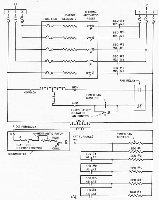

"Note that one of the limit controls in Figure 1 has a manual reset feature that would call your attention to a problem because it must be reset. That is not a great system when the heaters are above the ceiling like the call we were on. Both of these controls are very reliable and can function many times before failure occurs.
"The other limit type control is a one-time control that once it functions or opens, will not reset, and must be changed. There are two types of these, one that actually flaps open (Figure 3, top). When you look at one of these it is very easy to tell that it has opened. The other one looks like a small silver bullet and is opened internally when it functions (Figure 3, bottom). This control must be checked with an ohmmeter to see if it has an open circuit.
"These two controls that open and don't close are set at several degrees higher than the automatic reset or the manual reset. They may be set to open as high as 220 degrees F. As I mentioned, this is the last line of defense.
"Notice that all of the controls mentioned up to now actually open the line circuit. This will interrupt the power to only one side of the electric heater. We saw a heater on our service call that was burned in two, and one end of the wire was touching the frame and still heating. This can create two kinds of problems.
"First, I remember one service call that I had years ago where a system had switched over to cooling and would not cool the house. I checked the system and could not find anything wrong with the cooling. I finally checked the electric heat system and found two elements grounded and creating enough heat to cause the air conditioner to run all the time and not cool the house.
"Second, if the wire is touching the furnace frame and the furnace is not well grounded, it can become an electrical shock hazard. Any time you are under a house with an electrical system it is a good idea to push one lead of your electrical meter in the ground and touch the other to the appliance. If there is a voltage reading, shut the power supply off using your insulated screwdriver handle. What you have done with the meter is simulate what would happen to your body if it were to become an electrical path to ground. On wet ground, you don't have a chance if the frame is electrically hot.
"We have discussed the thermal safety control, often called the limit controls. We have not discussed the fuses in the system. The fuses are protection to the conductors, the wires servicing the heaters. They will also protect them from a direct short to ground, but not the type of ground you had on your service call. That ground had the resistance of the heating element still in the circuit."

Btu Buddy agrees, "Remember what I said earlier. There is a lot of energy potential in the area of an electric heat system. There is one other thing that is worth mentioning at this time.
"Since there is a lot electrical energy being used, the electrical connections used for electric heat must meet the code and must be maintained. Since these controls are sensitive to heat, the electrical connections must be correct or heat will be generated at the connections and may cause the control to open its circuit, even though the air temperature is not hot.
"For example, you should always use approved connectors when making repairs. There will be times when you will find that a wire has been hot to the point that it needs changing. The wire conductors are copper and if they are discolored, they have been hot. You should cut the copper wire back to where is copper colored and apply a new fresh connector that is approved for that connection to prevent it from happening again. When manufacturers size the wire inside the actual heater terminal box, the wire may be right on the borderline of being adequate. It may be carrying the maximum current for that wire size and the connections must be perfect for the system to work.
"I remember working in an industrial plant that used electric heat in the manufacturing area and it kept burning the fuses up. I checked the wire size and it was too small. I called the manufacturer and they said that it was adequate. They were no help at all. I finally installed small fans in the electrical control panel to prevent the problem from occurring, and it worked."
Bob asks, "How do you know what to do in a case like that?"
Btu Buddy says, "It was a matter of excess heat and the manufacturer did not want us to rewire the electrical panel. So we did the next best thing; we added ventilation. This is actually the job of the electrical department, but they had exhausted their means to make a repair and turned over to us, as it was a heating system."
Bob asks, "Will I ever be able to have that kind of judgment?"
Btu Buddy answers, "Yes, because you keep asking questions and reaching for solutions. You are on the right track, just don't get derailed."
Bill Johnson has been active in the HVACR industry since the 1950s. He graduated in gas fuel technology and refrigeration from the Southern Technical Institute, a branch of Georgia Tech (now known as Southern Polytechnic Institute). He taught HVAC classes at Coosa Valley Vocational & Technical Institute for four years. He moved on to become service manager for Layne Trane, Charlotte, N.C. He taught for 15 years at Central Piedmont Community College, part of this time as program director. He had his own business for five years doing installation and service work. Now retired, he is the author of Practical Heating Technology and Practical Cooling Technology, and continues as a co-author of Refrigeration & Air Conditioning Technology, 5th Edition, all published by Delmar Publishers. For more information, he can be reached at 704-553-0087, 704-643-3928 (fax), or bmj@myexcel.com.
Publication date: 04/19/2004

Report Abusive Comment