In one typical example, Lockheed Martin engineers are using computational fluid dynamics (CFD) software to ensure the effectiveness of the climate control system of the space vehicle. The engineers built a computer model of the X-38 and its contents, and used CFD to simulate the airflow and heat transfer throughout the vehicle's cabin, eliminating the costs of building and testing a physical prototype. Preliminary simulations showed some areas with potential ventilation problems due to equipment blocking airflows.
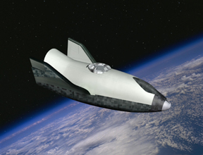
The X-38 is designed for use on the International Space Station (ISS) as an emergency crew return vehicle (Figure 1). It is for this purpose that the term "lifeboat" is used. One of the goals of the X-38 program is to build a human spacecraft for an order of magnitude less cost than ever before. In the late 1980s, prior to the X-38, one crew return vehicle was estimated to cost as much as $2 billion. The X-38 project is expected to build and test fly two prototypes in space for $90 million.
Several factors will contribute to the reduced cost. For example, the X-38 uses a lifting body design derived from the U.S. Air Force's X-24A experimental project in the mid-1960s. Additionally, parts of the X-38 will be bought over the counter, using existing, rather than newly designed technology - a marked difference from past NASA spacecraft.

Cold Climate
As an emergency escape vehicle, the X-38 will be docked to the Space Station and air will flow between the two modules. While in orbit, the amount of radiation from the sun and the earth that reaches the X-38 will vary, causing its surface temperature to fluctuate from 120 degrees C to-62 degrees C. In the cold environment, condensation is a concern, as scientists learned from the experiences of the MIR space station. When condensation builds up on the inner wall of a space vehicle, it can migrate virtually anywhere in the weightless environment of space. This can result in damage to sensitive electronic equipment or the growth of fungi.
The ventilation system of the X-38 was designed to deliver warm air to the inside walls of the X-38 cabin in order to maintain cabin wall temperatures above the dew point, the temperature at which condensation forms. Lockheed Martin engineers were asked to evaluate the effectiveness of the design of the cabin ventilation system for this purpose. A lumped parameter, finite difference based thermal design and analysis system called SINDA had previously been developed by NASA/JSC for evaluation of the X-38's thermal protection system (TPS) for the vehicle's external structure. The SINDA calculation is based on the conditions on the interior of the vehicle and on radiation levels calculated by another software package called Thermal Synthesizer System.
For the vehicle interior, a "perfect mixing" assumption, corresponding to uniform conditions, is made. Because this is not representative of the actual conditions inside the X-38, results using this approximation were considered insufficient for the analysis. Engineers wanted to determine the actual flow conditions within the cabin so that they could calculate more accurate heat transfer coefficients for input to the SINDA calculation.
Physical testing was ruled out because a physical prototype of the X-38 was not available and because testing would be very difficult, since the heating and cooling effects of the sun, earth, and space station on the X-38 exterior might be difficult to simulate in a test chamber. CFD simulation offered an alternative way to evaluate airflow within the vehicle by making it possible to visualize the flow field.
CFD provides a fluid velocity, pressure, and temperature distribution throughout the solution domain for steady-state or time-dependent problems with complex geometries and boundary conditions. Lockheed Martin engineers selected Fluent CFD software from Fluent Inc., Lebanon, N.H., for use on this project.
One of the main reasons for selecting Fluent was that it provides a powerful and mature program for performing a CFD analysis using an unstructured grid. Previous X-38 studies used a structured grid from another CFD software package to model a simplified geometry of the cabin walls and ventilation system, but it did not include the complex interior geometry in the present X-38 Fluent model. The current X-38 model was developed using Fluent in order to include the complex interior geometry of the cabin (Figure 2) and its potential effects on airflow, particularly close to the cabin wall. This complex interior geometry required an unstructured grid to model components that were both irregularly shaped and close to each other in proximity.
Model Development And Results
The first step in the CFD simulation was to create a digital representation of the X-38, including a detailed model of its ventilation system and the remaining interior geometry of the cabin, such as crew seats, electronics equipment, and the environmental control system. This was done in GAMBIT, Fluent's preprocessor for geometry creation and meshing. The X-38 geometry was imported in IGES format into GAMBIT from Pro/ENGINEER, a CAD system. This approach saved time by eliminating the need to create the geometry from scratch.Next, engineers developed the surface topology and surface mesh. Two features of the X-38 Fluent model - the use of virtual as opposed to real geometry, and the presence of "suspended" volumes and surfaces - required that the volume mesh be created in a separate Fluent preprocessor, TGRID. The presence of virtual geometry or "suspended" surfaces or volumes in a model can restrict GAMBIT from creating volume meshes. Based on the surface mesh, a volume mesh of 2,300,000 cells was created in TGRID for the X-38 model. The next step was to define the boundary conditions for the analysis, such as temperature and flow rate at the ventilation inlets to the vehicle, as well as thermal conditions at the cabin walls.
A special approach was taken in implementing boundary conditions. The X-38 cabin walls and floors include a structural frame shaped like a waffle grid, which protrudes inward from the cabin walls. This waffle-shaped grid can effect dramatically the flow of air along the inside cabin walls. Although the structural grid covers only the floor and the back wall of the cabin, including this geometry in the X-38 Fluent model potentially could dramatically increase the volume mesh size of the model. This could render the model too large to run on available computers.
Therefore, a separate Fluent model was created, which included a portion of the X-38 cabin floor, where the structural frame has some of the most dramatic relief features throughout the cabin. A similar model was developed of the same portion of the floor, but without the structural grid in place. Local heat transfer coefficients were predicted along the floor with and without the structural frame in place. The difference in the local heat transfer coefficients between the two models could then be used to adjust the heat transfer coefficients in the larger X-38 Fluent model, which did not include the structural frame.
The implementation of boundary conditions along the cabin walls required knowledge of the amount of heat transferred through the cabin walls to the exterior of the vehicle. It was therefore necessary to integrate results from the X-38 Fluent model with existing models of the X-38 thermal protection system (TPS) and exterior environment to space, in order to obtain a prediction of the amount of heat transferred through the cabin walls. This effort required a common nodal map across the cabin wall interface between the X-38 Fluent cabin and TPS model in order to exchange boundary conditions between the two models. Secondly, because the heat transfer between the two models is dependent on results from both models, the solutions are "coupled" and an iteration process was necessary in order to achieve an energy balance across the cabin wall interface.
Following the initial solution of the Fluent model, cabin wall temperatures predicted by the X-38 Fluent model were provided as boundary conditions to the SINDA model of the TPS. Subsequently, the TPS model calculated the heat flux through corresponding areas of the cabin wall. The heat fluxes provided by the SINDA model were then used as boundary conditions at the cabin wall in the X-38 Fluent model, and a second simulation was completed in the model with the new boundary conditions. This process was continued until both temperatures and heat fluxes at the cabin wall did not change between iterations of the two models.
Once convergence is achieved between the Fluent and SINDA models, local heat transfer coefficients predicted by Fluent inside the cabin walls are provided to the SINDA model. Heat transfer coefficients along the X-38 cabin wall and aft bulkhead, where structural grids are located, were further modified based on the results of the study previously mentioned. The SINDA model is then modified to use these local heat transfer coefficients to predict temperatures inside the cabin wall.
Due to the large volume mesh, the simulation in the Fluent solver required 24 hours using two parallel processors on separate, dedicated Hewlett Packard (HP) workstations. Separate HP workstations were needed due to the large memory requirements of the model, roughly 2 gigabytes. Two iterations between the Fluent and SINDA/TSS X-38 models were completed before results from the simulations began to diverge between iterations. Previous experience has indicated that when a divergent trend occurs between this type of CFD and SINDA/TSS model, convergence is not achievable. Therefore, further simulations were not attempted, and examination of the SINDA X-38 model indicated some of the conductance paths through the vehicle's external structure required modification.
Although convergence between the two X-38 models was not achieved, preliminary results showed that, due to the cramped quarters of the X-38, the ventilation system was not working exactly as its designers had anticipated. Pieces of equipment were blocking the flow of warm air to some of the walls. Supply air was also prematurely separating from the cabin walls. These phenomena were indicated by path lines depicting the flow of air as it traveled from the vents and moved throughout the vehicle.
Further Research
Modifications to the SINDA/TSS X-38 model are needed before any further simulations are attempted. Once these convergence issues are resolved, results from the Fluent X-38 model will make it possible to achieve substantially greater accuracy than could be achieved if it had been necessary to assume perfect mixing in the X-38 SINDA/TSS model. NASA engineers will use the information about airflow and heat transfer provided by the simulation to redesign the vehicle's ventilation system, or rearrange its contents, to improve the coverage of warm air on the walls. By using CFD software prototyping rather than physical testing to evaluate the condensation situation in the X-38, Lockheed Martin is helping NASA in its effort to build a less expensive space vehicle.Note: The X-38 project is currently suspended and is under review as a result of funding issues associated with the International Space Station.
Brad Eckhardt is with Lockheed Martin Space Operations, Houston, Texas, and Laith Zori is with Fluent Inc., Lebanon, N.H. For more information about CFD, contact: Fluent Inc., 10 Cavendish Court, Centerra Resource Park, Lebanon, NH 03766; 603-643-2600; 603-643-3967 (fax); www.fluent.com.
Publication date: 10/06/2003

Report Abusive Comment