The screw compressor is a positive-displacement rotary mach-ine. Compression is achieved by two intermeshing rotors housed in a suitable casing. The “male” rotor has four lobes of unsymmetrical profile sections formed helically along the rotor length. These mesh with the six corresponding flutes on the “female” rotor.
As the rotors turn, gas is drawn through the inlet port to fill the space between adjacent lobes. When the interlobe space along the rotor length is filled, the rotation of the rotors moves the end of the lobes past the inlet port sealing the interlobe space.
As the rotors continue to rotate, the intermeshing of the lobes on the discharge side of the compressor progressively reduces the space occupied by the gas, causing compression.
Compression continues until the interlobe space becomes exposed to the outlet port in the casing and gas is discharged.
Lubricating oil is injected into the compression chamber in most applications to absorb most of the heat of compression and to seal the running clearances between the rotors, enabling the machine to operate at high pressure ratios in a single stage.

The SUBJECT COMPRESSOR
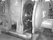
The compressor we will work with is a Howden Mark 1 WRV163/14550. This unit was selected as it is one of the smallest units in the WRV range of compressors. The Howden nomenclature for this unit can be broken down as follows:Mark 1 = The generation or release number. The 163-mm compressor is still in its first generation having been introduced in 1973. The 204 mm compressor in its sixth generation.
WRV = (W) Wet, oil injected; (R) refrigeration; (V) volume, capacity control.
163 = The diameter of the rotors in millimeters.
145 = The ratio of the rotor length compared to the diameter.
5.0 = The built-in volume index (vi) for the compressor.
XXX = The digits following the vi are the discrete serial number for that configuration compressor.
The correct and complete identification of a compressor is vital in obtaining technical support or the correct parts in the proper material of construction.
ANNUAL SURVEY
As a result of the compression process, forces are generated that must be absorbed by the compressor components. These forces are considered when a compressor is selected for an application. Components such as balance pistons and bearings are optimized for the forces created at the design conditions of service.The twin screw compressor is simplistic in its basic design but precise in its execution. In operation, the compressor is often subjected to system upsets and contamination in addition to the design loads. These conditions have a continuous effect on the few normal-wearing components. This inevitable wear, from conditions both obvious and unsuspected, is the reason an internal inspection is needed regularly.
The purpose of the suggested annual survey is to check for significant wear of the thrust bearings, slide valve guide block, or PTFE seals. The survey includes removing the hydraulic cylinder, outlet end cover, and the slide valve. Key parameters for inspection include gauging the rate of wear of the inspected parts.
This is the golden opportunity to troubleshoot any abnormal condition or high-wear-rate situation and rectify the root cause.
One of the attractions of the rotary screw compressor is lack of contact and wear of the major components. The basic compressor, if refurbished from time to time, can continue to perform its intended duty indefinitely. This major advantage is largely lost if the normal-wearing components are kept in service beyond their useful life.
When ignored or kept in service with clearances that are out of specification, the compressor is in danger of being damaged to the point of being beyond financially reasonable repair.
Too often, the compressor “failure” is actually a human failure. Compressor failures that occur due to accidents may not be avoidable; failures due to neglect are.

BASIC ANNUAL SURVEY
Safety first:Remove the refrigerant and lockout the electricals.Disassembly:
1. Drain oil from the hydraulic cylinder, both sides of piston.
2. Drain oil from the discharge cover.
3. Remove three-socket head cap screws and the aluminum cap.
4. Remove eight-socket head cap screws and the cylinder cover.
5. The spindle assembly can be removed with the cover.
6. Remove the stop sleeve, if fitted.
7. Move the slide valve to the “unload” position.
8. Unlock the piston lock washer; remove the piston nut.
9. Remove the piston using threaded ports for the purpose.
10. Fit the eyebolt to the outlet cover and support the weight.
11. Remove dowel pins, set pins, and pull the cover over the piston rod
(Figure 1). 12. Withdraw the slide valve (see Figure 2).
The compressor is now ready for your visual inspection.
Check thrust bearing axial float:
1. Insert a piece of 1/2-in. unscrewed rod into the discharge end of the rotor.
2. Set a dial indicator to the end of the rotor.
3. Using a push and pull action, record the indicator deflection (see Figure 3).
4. Maximum bearing float is 0.00011811 in.
Check journal bearings:
1. Remove the thrust bearing retaining plate.
2. Set up a dial indicator on the casing; take readings from the 12 o’clock position of the rotor or rotor locknut.
3. Insert a ½ -in. (13-mm) bar into the end of the shaft and lift (see Figure 4).
4. Deduct 0.001 in. from the reading and record.
5. Compare your readings with published clearances (0.0028/ 0.0043-in. nominal, 0.006-in. maximum).
Check rotor clearance:
Check slide valve/guide clearance:
Check PTFE parts for unusual wear:
Inspect rotors and main casing:
1. Working through the slide bore, inspect the rotors.
2. Record component conditions and any additional observations. If readings are within specification, the compressor can be reassembled using new O-rings, lockwashers, and PTFE rings.
It is extremely important that the fasteners on the thrust-bearing retaining plates of the 163-mm compressors are torqued exactly to the specified setting of 10 lb/ft. Over-torquing will not permit correct operation on the thrust bearings, resulting in premature failure.

FAILURE ANALYSIS
Mechanical seal— The input shaft seal is the most precise and most fragile component of any screw compressor. In many instances, it’s like the mine canary: It becomes the first point of observable distress.A key point is that multiple “seal failures” are rarely actual seal failures. What you are likely observing is the proverbial tip of the iceberg; the leaking seal might be a warning of a more deeply rooted problem.
Seal problems can be characterized as occurring in two general areas: primary face and secondary seal. A few of the conditions you may observe and likely causes are listed in Table 1. For repeated seal failures, don’t overlook the items listed in Table 2.

BEARINGS
A compressor’s bearings are among its most vital components. In addition to their antifriction qualities, compressor bearings locate the position of the rotors with great precision.Journal — The main bearing (hydrodynamic type) depends on a film of oil to keep the rotor and bearing surfaces separated. This thin film supports the entire weight of the rotor and its gas load. Bearings fail when this oil film becomes contaminated, breaks down, or if the bearing becomes overloaded.
The oil film is created and maintained by the lube oil system. At rest, the rotor journal is in contact with the bearing surface. With proper oil pressure, the rotor “floats” on the oil injected into the bearing cavity. Under design loads, the rotor rides on a lubricant wedge. Under normal operating conditions and a continuous supply of clean oil, the rotor and bearing surfaces remain separated. (See Table 3 for a listing of journal problems and their causes.)
Rolling element — The thrust bearings installed in the WRV163 compressor are paired single-row, angular-contact ball bearings. The steel-caged antifriction bearings are fitted face to face at the discharge end of the compressor.
The bearings are off-loaded by the use of balance pistons and sleeves installed at the discharge end of each rotor. Further off-loading of the male rotor thrust is achieved on some models by having another balance piston in the mechanical seal cavity at the inlet end of the male rotor. The 163-mm compressor achieves sufficient off-loading by utilizing a single balance piston on the input end of the male rotor. (See Table 4 for a listing of rolling element problems and their causes.)
The term “lubrication failure” does not usually imply a total lack of lubrication. A thorough investigation may reveal too low a differential oil pressure, improper viscosity due to dilution, or product condensing due to a low discharge temperature.

VIBRATION, NOISE
The inherent vibration and sound levels of a bare compressor are rather low. For the 163-mm compressor, the maximum vibration level is 0.2165-in./sec in the horizontal and vertical plane and 0.295-in./sec axially. These levels are measured in RMS velocity.While sound levels are subjective, changes in operating sound levels should not be ignored. The cause of abnormal sound/vibration levels can be rooted in the compressor drive, auxiliary equipment, or system gas flow. Noise from the motor, piping, vessels, etc., will increase the perceived sound pressure level in any installation, as will the acoustical environment and background noise where the compressor is installed.
When investigating abnormal vibration levels, don’t overlook the following:
The conditions and causes listed in the previous failure analysis were kept simple. In reality, several factors often seem to conspire, making the root cause of a failed component not always obvious. Only after a complete review of operating conditions and other compressor components can these be determined.
If it is determined that the compressor requires complete disassembly for repair or overhaul, the following additional steps should be followed.

COMPLETE DISASSEMBLY
The following details the disassembly procedure for a major overhaul.1. Remove the thrust bearings:
2. Remove the input shaft seal:
3. Remove the inlet end cover:
4. Remove the rotors:
Note: Assembly is performed in the reverse order, paying particular attention to published torque values and recording all clearances.

CLOSING THOUGHTS
Widener is North American customer support manager for Howden Compressors, 1850B N. Gravers Rd, Plymouth Meeting, PA 19462; 610-313-9800.
Sidebar: Failure Mode
The root causes of compressor failures can be numerous. However, they will be manifested in only a few ways:
The existence of any of these conditions will not indicate the area of fault, but should be the signal to perform an investigation to determine and rectify the root cause. Extra diligence when performing the annual survey would also be wise.
Publication date: 06/04/2001

Report Abusive Comment