
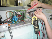
Figures 2 and 3 show the control circuit of a medium-size commercial ice machine. Notice that the microprocessor has replaced a lot of the hard wiring that used to be inside a machine of this nature.
This type of technology is often referred to as “clean technology.” In fact, 10 years ago, there would have been so many wires going in and out of controls that the entire control circuitry would have looked like a plate of spaghetti.
Now, most modern control circuits consist of a microprocessor (Figure 3), a few starting components like a start and run capacitor, potential relay, and compressor contactor (Figure 2), and the main loads or power-consuming devices. In this case, the main loads include the compressor, harvest motors, hot gas and purge solenoids, and water pump (not shown in the figures).
Most service techs are not afraid of the main loads or power-consuming devices when troubleshooting. It is the microprocessor that is the most feared. However, the microprocessor can actually be the simplest component to troubleshoot with a little patience, understanding, and practice.
The microprocessor is actually a small computer that has a sequence of events stored into its memory. It has many sophisticated, solid-state devices in its internal circuitry that are needed for its proper operation. However, a service technician does not need to know how to troubleshoot or understand how each solid-state device operates in order to tell if the microprocessor is good or bad.
What the service technician does have to know is the microprocessor’s sequence of events, its self-diagnostic functions, and how to input/output (I/O) troubleshoot the microprocessor using its external terminals.
The microprocessor’s external terminals are shown at the right- and left-hand sides of Figure 3, where most of the wires are coming into and out of the microprocessor. These wires are the inputs and outputs.

Sequence Of Events And Self-Diagnostics
The sequence of events of a microprocessor are usually found in the service manual. However, too often a service manual cannot be found on-site with the piece of refrigeration equipment. In this case, the owner or manager of the establishment where the refrigeration machinery resides must be contacted to see if they have filed the service manual away in some “safe” location.If the service and operations manual cannot be located, the company that manufactured the equipment must be contacted.
Usually a model and serial number of the refrigeration machine are all that are needed to pinpoint the manual by a company employee. All the service tech really needs is a few pages out of the manual that include the sequence of events of the microprocessor, and how to initiate the self-diagnostics of the machine, if it has any.
Simply ask the company employee to fax these pages from the manual. With today’s technology, this information can be in the hands of the service technician in a matter of minutes.
Figures 4 and 5 show a few pages from a service manual of an icemaker. The manufacturer has included the step-by-step sequence of events and the self-diagnostics of the microprocessor, respectively. Now the service technician has the knowledge of what the ice machine is supposed to do at a certain time or temperature.

Input/Output Troubleshooting
I/O troubleshooting a microprocessor is actually easy if some common sense is used on the service tech’s part. All that is needed are a voltmeter and knowledge of the sequence of events from the service manual.An ohmmeter should not be used directly on a microprocessor because of the ohmmeter’s battery voltage. Many times this voltage is too high and may damage the intricate, solid-state components and/or the magnetic memory internal to the microprocessor.
However, if certain components (inputs and/or outputs) to the microprocessor are detached from the microprocessor, an ohmmeter can then be safely used.
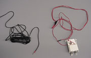
Microprocessors are fed with information from their input devices to their input terminals. Input devices can be analog as with a thermistor (variable resistor) or digital (on-off) as with a switch. Figure 8 shows a thermistor on the left and an ice thickness switch to the right. After processing the data from the inputs, an output signal is sent. The output signal can be read with a meter from the output terminals of the microprocessor.
Input and output terminals of a microprocessor can be seen in Figure 6. Notice that both the input and output terminals of the microprocessor are clearly labeled for the service technician to troubleshoot. It is from these input and output terminals that most troubleshooting can be accomplished using a meter.
Most of the time, the input signals are low-voltage (ac or dc) or resistance signals; the output signals are of higher voltage (usually ac) going to the power-consuming devices — but not always. Refer to the service manual for specifics. Many times, input devices are for nothing but the digital readout for a condensing temperature, evaporating temperature, or a sequence mode.

Troubleshooting Example #1
A technician is servicing an icemaker and has determined that the ice machine will not come out of a hot gas defrost mode as quickly as it should. Too long of a defrost will cook off the metal coating on the evaporator.Instead of the harvest motor’s probe pushing the ice off the coil, which will terminate defrost with a curtain switch, the evaporator gets very hot from the prolonged hot gas defrost. In other words, a “cook-out” occurs. The ice slowly falls off the evaporator in chunks by gravity. Sometimes one of these chunks will trip the curtain switch and bring the machine out of defrost; other times, it will not.
The technician takes out a voltmeter and measures the output terminals of the microprocessor labeled motor 1 and motor 2 while in defrost (Figure 6). The technician measures 115 vac at both terminals and determines that this is the correct voltage.
This process told the technician that the microprocessor was doing its job and sending an output signal to the harvest motor. The microprocessor is not to blame. The problem must lie either in the harvest motor or the wires leading to the harvest motor.
The technician then checks voltage at the harvest motor itself and gets 115 vac. This check eliminated the problem being in the wiring between the microprocessor and the harvest motor.
The problem then must lie in the harvest motor itself. The technician knows that if the correct voltage is going to a power-consuming device, and the power-consuming device is not operating, the problem lies within the power-consuming device.
The technician then retrieves a new motor from the service van and installs it. The new motor works perfectly and the ice machine is watched for two complete cycles. Everything works as it should.
Figures 3 and 7 show a technician measuring the voltage into and out of a microprocessor, respectively. It is important that the technician use as short a measuring probe as possible to avoid electrical shorts to other terminals of the microprocessor. A direct short could ruin any microprocessor. Taping your voltmeter probes halfway up will often prevent electrical shorts when measuring inputs and/or outputs from a microprocessor.

Troubleshooting Example #2
A technician servicing an icemaker that has a microprocessor observes that the ice machine will not come out of its “ICE 1” mode.The technician then consults the service manual and finds out that the evaporator must reach 14° before an internal timer will start (Figure 4). The technician wonders if it is the microprocessor’s fault, or if is it in one of the inputs to the microprocessor.
The technician then reads the manual further and discovers that the microprocessor is fed an input signal from a thermistor connected to the evaporator. A thermistor is nothing but a resistor that varies its resistance as the temperature changes (Figure 8). This thermistor is what signals the digital light-emitting diode (LED) display as to what mode the icemaker is in (Figure 1). It is this thermistor that also will tell the microprocessor when the evaporator has reached 14°.
The technician reads further and finds out that the manufacturer has supplied a resistance vs. temperature relationship table for checking thermistors. The only sure temperature that the technician knows s/he can simulate accurately is 32°. This is accomplished by placing some crushed ice in a small amount of water and stirring. The thermistor lug is then taken off of the evaporator and is also electrically disconnected from the microprocessor’s evaporator input terminal (Figure 6).
The thermistor lug is given a chance to stabilize its temperature at 32° in the ice water bath. A resistance reading is then taken with an ohmmeter. The reading is 5.50 thousand ohms, or 5.50 Kohms.
According to the temperature vs. resistance chart for the thermistor, the resistance should be 9.842 Kohms. This indicates a defective thermistor and explains why the microprocessor is not going out of ICE 1 mode. A new thermistor is ordered from the manufacturer.
The technician could have measured the signal coming into the microprocessor’s input terminal labeled “EVAP” (Figure 6), but only if s/he knew what it was supposed to be. Most of the time these signals are a low ac or dc voltage, but sometimes can be a resistance signal. The technician must read the manual to find out.
Self-Diagnostics
Many microprocessors come with a self-diagnostic or component test mode built in.Figure 5 walks a technician through the steps to accomplish the test. These tests usually allow the technician to distinguish between a defective microprocessor, a defective power-consuming device, or circuitry between the two. Again, these tests involve troubleshooting the microprocessor’s output terminals.
Many times, error codes can be read directly off the LED display. This is a valuable troubleshooting and time-saving tool. However, usually regularly occurring problems, not all problems, can be diagnosed with error codes.
A word of advice: Always check to see if the fuse on the microprocessor is good before condemning the processor. Most microprocessors have these fuses.
As one can see, the microprocessor is not as complicated as it seems to the service technician. All the technician really has to know is I/O troubleshooting, understanding the sequence of events, and how to find and follow an instruction manual.
Tomczyk is a professor of hvac at Ferris State University, Big Rapids, MI, and author of the book Troubleshooting and Servicing Modern Air Conditioning and Refrigeration Systems, published by Business News Publishing Co. To order, call 800-837-1037.

Report Abusive Comment