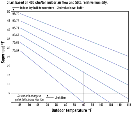
However, the same underlying principle holds for all tables and curves. Figure 1 is an example of a superheat-charging curve instead of a table. The curve is based on 400-cfm/ton airflow at 50% relative humidity across the evaporator coil. The steps to charge a system according to this curve are listed below.
1. Measure indoor drybulb temperature (DBT). This is the return air at the air handler. Note: Use wetbulb temperature (WBT) if the percentage of relative humidity is above 70% or below 20%.
2. Measure outdoor DBT at the outdoor unit. This is the condenser in air temperature.
3. Measure suction pressure at the compressor and convert it to a temperature using a pressure-temperature chart.
4. Measure compressor in temperature on the suction line near the compressor.
5. Calculate the amount of compressor superheat. Compressor superheat is all the superheat the compressor “sees.” It is a combination of evaporator and suction line superheat. Compressor superheat is sometimes referred to as total superheat.
6. Find the intersection where the outdoor temperature and indoor temperature meet; read degrees superheat.
If the compressor superheat of the system is more than 5?F higher than the chart reads, add refrigerant vapor into the low side of the operating system until the superheat is within 5? of the chart.
If the compressor superheat of the system is more than 5? below what the chart reads, recover refrigerant until the superheat is within 5? of the chart.
Note: Always let the system run for at least 15 min after adding or recovering refrigerant from the system before recalculating compressor superheat.
Also, if the system is using a newer alternate refrigerant that has a temperature glide and will fractionate, liquid refrigerant has to be throttled into the low side of the system while the system is running to avoid fractionation.

R-22 example
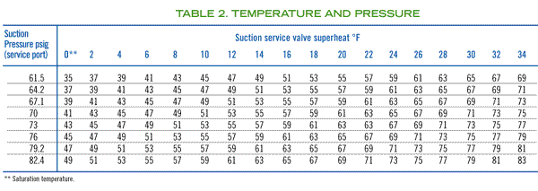
Let’s consider an R-22 capillary-tube or fixed-orifice system. The indoor DBT = 80?; outdoor DBT = 90?; suction pressure at the compressor = 60 psig or 34? using the pressure-temperature chart (Figure 2); compressor temperature on suction line = 54?; and compressor superheat = 20? (54?-34?).The intersection of the 90? outdoor temperature with the 80? indoor temperature says that there should be about 17? of compressor superheat. Our system has 20? of compressor superheat. This is within 5? of the superheat chart, so the system is fully charged and the technician would not have to add any refrigerant to the system.
The theory behind these tables and curves is simple. Let’s take the curve in Figure 1 for example. As you move to the right on the bottom axis, the outdoor temperature rises.
Notice that for a constant indoor DBT or WBT (lines that slant downward from left to right), as you increase the outdoor ambient temperature, the operating compressor superheat decreases. The reason for this is that there is now more head pressure pushing the subcooled liquid out of the condenser’s bottom through the liquid line and the capillary tube-metering device.
This will force more refrigerant into the evaporator and give less superheat. And this is why some systems will flood and slug liquid at hot outdoor ambients when they are overcharged. The superheat curve will prevent this from occurring if followed properly.
Referring again to Figure 1, if we assume a constant indoor DBT across the evaporator coil of 75?, and increase the outdoor DBT from 70? to 105?, we can see that the operating compressor superheat will fall from 23? to 0?. This is caused by the hotter outdoor ambients resulting in higher head pressures, which push more liquid through the capillary tube and into the evaporator.
So, it is normal for the system to run 23? of compressor superheat when the outdoor ambient is 70?. Do not add any refrigerant to this system, because if the outdoor ambient climbed to 95? later in the day, the system’s compressor would slug or flood from liquid refrigerant reaching it.
Note: If the relative humidity is above 70% or below 20%, use WBTs instead of DBTs across the evaporator coil to compensate for the varying latent (moisture) loads.
Another interesting point about Figure l is if the outdoor temperature stays constant and the indoor drybulb or indoor wetbulb temperature increases, the operating compressor superheat will increase. This increased loading of the indoor coil with either sensible or latent heat, or both, will cause more rapid vaporization of refrigerant in the evaporator. This will cause high compressor superheats and is a normal occurrence.
Many technicians will add refrigerant in this case and overcharge the system. However, it is completely normal for a capillary or fixed orifice metering device system to run high compressor superheat at high evaporator loading.
Troubleshooting
Referring one more time to Figure 1, as the outdoor ambient stays constant at 95? and the indoor DBT across the evaporator coil rises from 75? to 95?, the operating compressor superheat will rise from 6? to 33?. At a 95?, indoor air DBT and a 95? outdoor air DBT, the superheat should normally be 33? according to the chart.This seems like an inefficient system with an inactive evaporator and is the greatest disadvantage of a fixed-orifice metering device. However, this is the only way to prevent slugging and flooding of refrigerant with varying indoor and outdoor loads that air conditioning systems experience.
The main advantage of fixed-orifice metering devices is their low cost. If this system had a TXV as a metering device, it would control a constant superheat and keep the evaporator active at high- or low-heat loading. This is because the remote bulb of the TXV is a feedback mechanism that tells the TXV what the evaporator superheat is at all times.
Technicians are often hesitant to measure and use WBTs when working on air conditioning systems. However, it is important to get these measurements when in the field. WBT gives an indication of both the latent (moisture) and sensible heat loads on the coil. A simple thermocouple with some moist cotton wrapped around it, placed in a hole drilled in the air duct, will suffice.
There are also more sophisticated devices on the market for measuring WBT. A psychrometer is probably one of the most popular. It consists of a sock wrapped around an ordinary drybulb thermometer.
Psychrometers that are slung around a swivel connection are referred to as sling psychrometers. The technician simply wets the sock with distilled water and places it in the airstream until a temperature stabilizes. With both a DBT and WBT, the technician can get the percent relative humidity of the air by referring to charts or graphs. Some manufacturers provide a slide-rule superheat-charging calculator.
All of these means of charging air conditioning systems operate on the same theory described above.
As one can see, charging capillary-tube and fixed-orifice systems in air conditioning applications follow pretty much the same underlying theory.
However, it is strongly recommended to consult with the manufacturer of the a/c system to use their exact methods of charging using their charging curves and tables. Some manufacturers use different curves and tables for different models of their equipment. Other manufacturers have eliminated the need for a WBT because of custom-made charging curves that represent their laboratory tests on the equipment.
In general, however, the charging table in Figure 1 can be used with all capillary-tube and fixed-orifice air conditioning systems if a WBT and DBT are used, and the 400 cfm/ton (±10%) of evaporator air is established.

Orifice-specific curves

Often, separate charging curves and/or tables will be created for capillary tube and fixed orifice systems.
Figure 3 shows a set of two tables used for charging a 3-ton, split, residential, R-22, air conditioning system incorporating an orifice as the metering device. The condensing unit was precharged from the factory. A line set of 50 ft was used in this split-system application.
Extra refrigerant charge had to be added simply to fill out the extra volume of the suction line and liquid line within the line set. Often, manufacturers will specify how much extra charge to add to split air conditioning systems according to which evaporator was used and how long the line set is.
Longer line sets and other indoor coil matches may require additional charge. The technician must follow the manufacturers’ instructions to find out how much extra charge to add to these systems.
The two tables in Figure 3 are used to properly charge this split system. The following are instructions from the manufacturer:
With the superheat value obtained in Table 1 of Figure 3 and the suction pressure value, find the intersection of the values in Table 2 of Figure 3. This value is the required compressor inlet temperature taken at the suction service valve.
Again, if you aren’t sure how much refrigerant charge to add or recover, always consult the manufacturer for a copy of charging tables or curves. This information could be a simple phone call, fax, or e-mail away.

Report Abusive Comment