Adequate combustion air supply is a critical aspect of safe operation for any fuel-fired equipment. To provide this essential component, openings constructed of metal ducts or fixed grilles are typically installed to provide air from the outside or an adjoining part of a building.
Since combustion air openings are ducts, let’s look at the variables affecting airflow through them. As you read, consider this: Do you overlook this indispensable element of a well-performing and safe system? Let’s find out what makes them work and consider some additional installation methods.
AIRFLOW BASICS
To understand the operation of combustion air openings, it’s a good idea to review some airflow basics. For airflow to move through a duct, there must be a pressure difference across it created by an external source. Traditional installations depend on natural forces to create this pressure difference.
Here’s a summary of these forces:
- Air takes the path of least resistance;
- Air moves from a higher pressure to a lower pressure;
- Heated air rises, colder air falls;
- 1 cfm in = 1 cfm out; and
- Airflow can’t read a code book or follow arrows (I know, obvious, right?).
Knowing this, think about how these forces could be controlling combustion air in your installations.
COMBUSTION AIR CONFIGURATIONS
The typical combustion air installation most of us are familiar with dates to the 1950s. This was when two openings were established to provide proper ventilation into a confined space with fuel-fired equipment in it. To this day, we commonly use 1 square inch of opening per 1,000-4,000 Btu of input as a rule for sizing from this period.
There are three commonly installed combustion air configurations. They are ducted horizontally, vertically, or through a louvered door.
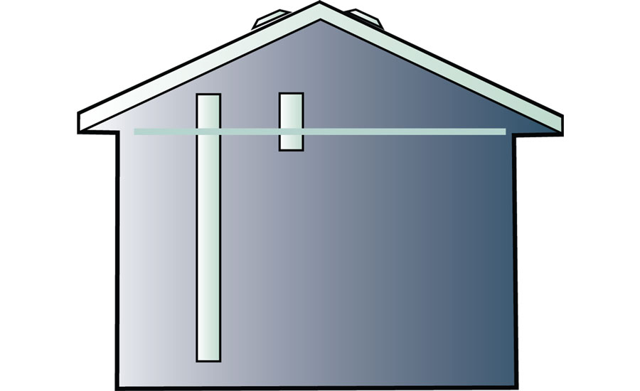
Horizontal combustion air ducts are required by code to have one duct installed 12 inches from the top and bottom of the mechanical room. They are typically connected to a heated part of the building or directly outside. Common sizing protocols for these ducts state the need for 1 square inch per 1,000-Btu input for ducts terminated in an adjoining heated area and 1 square inch per 2,000-Btu input for ducts terminated directly to the outdoors.
Vertical combustion air ducts are also required by code for one duct to be within 12 inches of the top and bottom of the mechanical room. These ducts are usually terminated to the outdoors or an area communicating with the outdoors, such as an attic or crawlspace. Vertical installations allow more input per square inch of opening than horizontal installations. Ducts tied directly to the outdoors or areas communicating with the outdoors, such as an attic or crawlspace, need 1 square inch per 4,000-Btu input.
Louvered doors are the last type of combustion air opening we typically use. They join the equipment with the rest of a building through the access door to the mechanical room. Sizing is usually ignored with a louvered door, and the one that closest fits the rough opening is used. An important item to remember with this type of installation is communication between the room and any airflow interactions taking place in the rest of the building.
COMBUSTION AIR INFLUENCES
Since natural forces control air movement through a combustion air opening, consider the influence of wind on horizontal installations. If combustion air ducts are installed where wind blows into them, all is well. The room is pressurized with air blown into the space.
What do you think happens to combustion air ducts installed on the opposite side of a building where the wind doesn’t blow? If you guessed they would pull air out of the room, you’re correct. Our industry has missed this interaction for decades.
Vertical installations are also subject to the fundamentals that drive air movement. These openings often exhaust air from a room instead of supplying it. This is due to a phenomenon known as stack effect, which is driven by heated air rising. Flow through these ducts reverses as warm air rises, escaping the building.
To visualize this for yourself, hold a piece of single ply toilet paper at the bottom of these ducts and see what happens. If you see the toilet paper pull into the duct, it is exhausting air. Instead, it should blow the toilet paper into the room, indicating air is flowing inside. Unfortunately, if air does flow in, you might have larger problems to deal with since it isn’t the norm.
These openings are two-way paths and can easily pull air out of a room instead of supplying it. If air is exhausted through a combustion air duct, we should question where the air to replace it is coming from. The source can easily be from a flue pipe.
Now, let’s consider the impacts of air balancing, duct leakage, central returns, interior door closure, and large exhaust fans. They can create large airflow imbalances and create a massive competition for combustion air. Another unfortunate side effect is this can also make fuel-fired equipment unsafe due to flue gas spillage.
COMBUSTION AIR SOLUTIONS
Fortunately, there are solutions to these problems if you use your knowledge of airflow the right way. The same forces that cause combustion air openings to reverse can be used to correct them. Ironically, some of these solutions might be viewed as code violations.
Combustion air traps can be used to keep warm air from rising and exhausting through the combustion air openings. A plug of colder air in the trap prevents the stack effect by using air density differences in a corrective way. On round ducts, they are commonly installed using elbows back to back to form a trap or by placing a 5 gallon bucket under the lowest duct.
Fan-powered combustion air can be used to overcome natural influences that reverse the flow of combustion air. Outside air is brought in through a dedicated fan and used to pressurize a mechanical room when equipment is in operation. It can also be interlocked with safeties to provide an additional layer of safety to prevent equipment operation if the fan fails to energize.
TIME TO STOP ASSUMING
Combustion air requirements are consistently established by national codes, but the flow of air through these openings is clearly left to chance. Do the current sizing protocols account for a means of consistent airflow to equipment relying on natural air movement alone? I’m hoping you begin to question this assumption.
We are starting to truly understand the impacts of these installations, since they are now being measured. The good news is you can measure the performance of your combustion air ducts, too, so you can verify what is happening to your installations.
A quick draft pressure measurement will provide you a tremendous amount of information about air movement in a combustion air duct and a flue pipe. With the test instruments and training available today, it’s time we stopped assuming combustion air performance and started to consistently deliver the right amount of air.
Publication date: 7/31/2017
Want more HVAC industry news and information? Join The NEWS on Facebook, Twitter, and LinkedIn today!


Report Abusive Comment