
In residential and light commercial HVACR, we work with run capacitors every day, and you may have noticed that they fail quite often.
Because of this, many companies are beginning to integrate capacitor testing into their regular diagnoses and maintenance practices, and I applaud this; however, it does lead to a debate on how to do it.
Many techs shut systems down, discharge the capacitors, remove the leads, and test with capacitance testers on their multimeters.
There are situations when this makes sense, such as when the system is already off; the motor is not running at all and the capacitor is a suspected cause; or with many blowers, where the capacitor and blower wires are not located in a safe or convenient place for run testing.
Most of the time, when a capacitor is being tested, it is to ensure the μF (microfarad) rating of the capacitor matches the rating listed on the capacitor. This can be done another way, and I would argue, a better way.
WHAT IS A RUN CAPACITOR?
A modern run capacitor is nothing more than two sheets of thin aluminum foil or “plates” with a thin sheet of plastic insulation between them all rolled up. When you stretch out an average compressor run capacitor, the foil can extend several feet in length. The inside of the capacitor is filled with an oil that helps to dissipate heat from the capacitor, and metal run capacitors have a plastic insulating liner that separates the metal from the oil.
A capacitor stores and releases electrical energy during every cycle change. A run capacitor is specifically sized to create the ideal phase shift for optimal running efficiency and power usage by the motor.
Contrary to what you will hear, a capacitor does not “boost” the voltage or create any extra energy. It only stores and releases energy, which results in more or less phase shift and more or less capacitive reactance or “capacitance,” as we often refer to it.
Some techs will point to the fact that when they place a voltmeter, they receive a reading that’s higher than the applied input voltage — they’ll often observe voltages of 300-400 vac between the Herm and C terminals (run and start) and assume this means the capacitor is boosting the voltage.
This higher voltage is actually due to the counter electromotive force (CEMF), or back electromotive force, produced by the motor itself. As the motor runs up to speed, it generates voltage into its windings counter to the voltage being applied, which results in a higher voltage between the compressor start terminal/capacitor HERM terminal, and the compressor run terminal/capacitor C terminal. This is why capacitors are rated for a higher voltage (370 or 440 vac) than other components in the system.
WHY DO RUN CAPACITORS FAIL?
Because a run capacitor is a fairly simple component with no moving parts, the only potential cause of failure is overheating, which causes expansion and the commonly seen bubbled top. This can be a combination of a high-start winding current and ambient high temperatures, or a high-voltage condition that results in a breach between the plates or the ground.
These circumstances generally result in an open capacitor that reads 0μF.
We often see run capacitors that aren’t failed, at least not completely, but are reading lower than the rated μF by more than the tolerance allowed by the manufacturer.
This can really only be caused by a breakdown in the thin aluminum sheet plates inside the capacitor, and it happens often.
When a capacitor becomes weak enough that it falls below the manufacturer’s specified rating, it will cause higher motor amps, higher motor temperatures, and lower power factors, which result in more inefficient power utilization.
Thus, if you aren’t testing for weak capacitors, you aren’t doing your customer any favors.
TESTING A RUN CAPACITOR
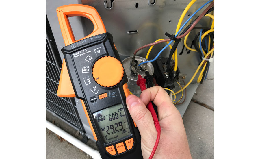
When testing a run capacitor, many techs pull the leads off and use the capacitance settings on their meters to test capacitors. When you’re constantly checking capacitors as a matter of regular testing and maintenance, testing the capacitors under load (while running) is a great way to confirm the capacitor is doing its job under real load conditions, which is also more accurate than taking the reading with the unit off.
When the unit is running, you are applying the actual voltage, amperage, and temperature the capacitor operates under every day, therefore giving you a more accurate reading. If your multimeter reads voltage and amperage accurately, this test does work. If the results aren’t matching up with your capacitor tester, you will want to check your multimeter against some other high-quality meters to see which reading is coming up incorrect, but the test under load procedure is sound math, and it works.
First, if you are used to doing capacitor checks during the cleaning stage of a preventive maintenance visit, you are going to need to change your practices and do your tests during the testing phase. These readings will be made at the same time you are taking other amperage and voltage readings during the run test.
Here are the steps:
1. Measure the amperage of just the start wire (wiring connecting to the start winding). This will be the wire between the capacitor and the compressor. In the case of 4-wire fan motors, it will usually be the brown wire — not the white-striped brown wire. In the case of a compressor with a dual capacitor, it will be the wire going to the HERM terminal. Note your amperage on this wire.
2. Now, take the amp reading you took on the start wire (wire from the capacitor), and multiply by 2,652 (some say 2,650, some 2,653, and some 2,654, but 2,652 is perfectly accurate). I remember 2,652 because 26 doubled equals 52.
3. Next, measure voltage across the capacitor. For a compressor that would be between HERM and C, this is the measured voltage across the start and run terminals on the motor.
4. Divide the total of the start wire amps times 2,652 by the voltage you just measured. This total is the capacitance. The complete formula is:
Start Winding Amps x 2,652 ÷ capacitor voltage = microfarads.
5. Read the nameplate MFD on the capacitors and compare to your actual readings. Many capacitors allow for a 6 percent +/- tolerance. If outside of that range, then replacement of the capacitor may be recommended. Always double check your math before you quote a customer.
6. Repeat this process on all of the run capacitors and you will have assurance whether they are fully functional under load or not.
7. Keep in mind that the capacitor currently installed may not be the correct capacitor. The motor or compressor may have been replaced, or someone may have put in the wrong size. When in doubt, refer to the data plate or specs on the specific motor or compressor.
So, let’s say you read a start winding amperage of 4.4 x 2,652 = 11,668.8 divided by a measured voltage of 335 V = 34.83 μF.
If the run capacitor was rated at 35 μF, this would be within range.
If it was rated at 40 μF, it would be 15 percent out of range, which is outside of the allowable range for all run capacitors I know of.
Since I started training with this method, I have often been asked where this calculation comes from. It is actually a simplified version of the equation to find capacitative reactance combined with a version of Ohm’s Law: Xc = 1/(2 x π x ƒ x C) and E = I x Xc.
I’m taking the 1/(2πƒ) part, multiplying by the measure we’re looking for (microfarads or millionths of a farad). This gives us the capacitative reactance, which, multiplied by the amperage and then divided by the voltage, gives us the capacitance. So you get: Xc = 2,652 and E = 4.4 x Xc = 11,668.8, so that 11,668.8 ÷ 335 V = 34.83.
To simplify, we can use approximate numbers and just call it amps times 2,652. Then, divide by the voltage.
This seems more complicated than just disconnecting and measuring directly, so why would you go through all that trouble? This is all so you can test the capacitor under real load conditions, which might just be enough to actually see that on-the-edge or flaky capacitor actually doing what it does, so you and the customer can be much more confident in your diagnosis.
Not very convincing? Maybe I could mention how this is faster than having to shut the unit off and then test? Maybe point out that this can reduce the risk of leaving a loose capacitor connection. What about how fancy you can look, staring at the calculator, while stroking your chin pensively? Scratch that last reason; that is likely just me.
So, test the capacitors while the system is running for a more accurate reading, and it works doubly in your favor as a way to impress other technicians with your newly found math skills.
Remember it’s just start winding amps x 2,652 ÷ capacitor voltage = microfarads.
Publication date: 6/12/2017
Want more HVAC industry news and information? Join The NEWS on Facebook, Twitter, and LinkedIn today!


Report Abusive Comment