While recently eating dinner with my colleague Paul Wieboldt, we started talking about the common defects found in many duct systems today. As we listed the various duct system flaws typically encountered by HVAC professionals, our conversation started to change.
We began imagining what the ideal duct system would look like. Instead of focusing on the poor work our industry has been plagued with, we decided to dream about how an ideal duct system could be built.
We questioned how such a duct system would be designed, fabricated, and assembled and outlined the components it would use, the materials it would be made of, and how it would be tested. Here’s a peek into what we came up with.
THE DESIRED OUTCOME
We first focused on what the desired outcome of the ideal duct system would be. We had to know what we were aiming for before we could begin describing what it would include. Oddly enough, our first outcome came from a customer’s viewpoint. We focused on the system being invisible to them.
For the system to be invisible, customers shouldn’t see it, hear it, smell it, or feel it. They shouldn’t know when the system comes on or when it shuts off. How many of your customers have to turn up the volume on their TVs when their systems come on?
As the system is running, its operation should be quiet — no loud noises coming from the return grilles or supply registers due to excessive air velocities. In addition to being quiet, there would be no drafts coming from the supply registers when the system is operating.
The second outcome we discussed focused on overall comfort. Even temperatures would be one of the main benefits of the ideal duct system. Conditioned air delivered into the building should be properly mixed, which would result in no drafts and complete this invisible part of the duct system.
Each room in the building would have the proper amount of supply and return airflow. There would also be no pressure imbalances in these rooms to influence humidity, dust, or other IAQ issues.
Based on those outcomes, we moved our discussion to design. We agreed to ignore industry rules of thumb to achieve the ideal duct design.
DUCT SYSTEM DESIGN
The first thing we both agreed upon was to immediately chuck the 0.10 rule of thumb as the reference point on a slide duct calculator. Too many duct systems have been sized incorrectly over the years due to this flawed design assumption. Our ideal duct system would be designed to operate in the mid-static pressure range of a high-efficiency, variable-speed fan.
Proper design would also account for smooth airflow through the system and avoid turbulence as much as possible. The pressure drop of components, like air filters and coils, would be accounted for in this design, too. Restrictive filters and coils would be avoided with lower pressure-drop components used in their place.
Conditioned rooms would have supply ducts and a return duct. We’d have no returns in the kitchens, bathrooms, closets, or utility rooms. We would strive for room pressures to be controlled and as close to neutral as possible.
Register selection would be based on the requirements of the room to account for throw, spread, and drop of conditioned airflow. Return grilles would be oversized to keep the system quiet. The registers and grilles would also be placed in a location that prevents short-circuiting of conditioned supply air back into the return grille.
Outside air would be brought in for ventilation purposes and balanced to customer needs. Depending on outside air conditions, ventilation air would be conditioned or dehumidified.
DUCT CONSTRUCTION
As our design discussion ended, we moved to the construction of the duct system, and we agreed, duct material doesn’t matter. Sheet metal, duct board, flexible, or any combination of duct material types would all be suitable to construct an ideal duct system.
Contrary to popular belief, duct material isn’t the main factor determining how well a duct system performs. Each material has pros and cons and works great when installed correctly. Those in our industry considering banning certain types are all suitable when it comes to constructing the ideal duct system.
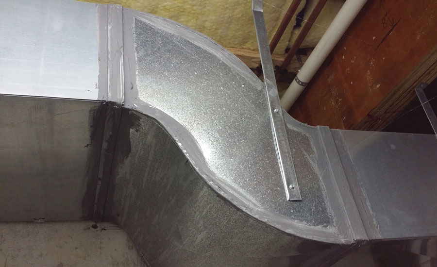
Our ideal duct system would have long transitions to prevent turbulent airflow. Elbows would have curved throats to maximize the Coanda effect, allowing airflow an easy path to follow. In square-throat elbows, single-wall turning vanes could also be used to direct airflow. Double-wall turning vanes are a no-no in our duct system because of their excessive pressure drop.
Our ideal ducts would be insulated with the highest effective R-values we could put around them. The rated duct insulation R-value would be less important than how well it actually performs in the field. Some duct insulation materials have great R-value ratings but fail to perform when they’re tested in the field.
BRANCH DUCTS
Each branch duct would have a damper to control airflow. Both supply and return branches would have a damper to control airflow on both sides of the system. The damper blades would be installed out of any turns to prevent them from having a negative effect on airflow.
Branch duct takeoffs would be at least be 12-18 inches away from the end cap. We would try to use all properly spaced side takeoffs to help prevent temperature stratification in the ducts. The takeoffs would be built on a 45-degree angle to allow easy air entry. Additionally, the duct would be one duct size diameter oversized to allow for easier air entry into the fitting.
Flex duct branches would be pulled tight; suspended every 3 feet; and have long, sweeping bends, when needed. If attached to any straight boots, there would be an insulated, well-supported sheet metal elbow attached to the boot for smooth airflow to the supply register.
DUCT VERIFICATION
The best duct design and materials are useless if you don’t verify they’re working together correctly. Ensuring the duct system performs as intended is a must.
So, we would air balance the duct system to within 10 percent of required airflow in each room. We’d also measure static pressure and verify it against manufacturer specifications.
We would aim for ducts with zero duct leakage, which is much easier to talk about than actually achieve. Ducts wouldn’t leak any conditioned air from the supply or into the return. This is necessary for successful air balancing and to prevent potential air quality issues.
BACK TO REALITY
To achieve the ideal duct system, everything we discussed here needs to be considered — not just the aspects enforced by code. The realities of what we have to deal with in the field often get in the way of perfection. Space limitations, rooms with crazy loads, duct location, building insulation, access to ducts, finished ceilings, and tight crawl spaces all hinder what we can realistically do in the field.
Anyone can design or demand the ideal duct system on paper, but, the reality is, we have to deal with the existing housing stock and what customers are willing to invest in.
Most customers won’t agree to the “Thou shalt have the ideal duct system” mentality. Our job is to get them as close to ideal as we can given the amount they’re willing to invest.
We need to persuade them why it’s the best choice and have confidence they will make the right decisions when presented with the right information. Some will make the right choices, others won’t. Don’t condemn them because they didn’t choose your vision of perfection.
I hope you enjoyed a peek into some of the points we brought up in our conversation. I certainly don’t claim to have all the answers to the ideal duct system, but I have tested and corrected enough to know what works and what doesn’t.
I would love to hear your ideas for the ideal duct system in your part of the country. What are you doing to ensure your customers feel they’re getting the ideal duct systems?
Publication date: 11/28/2016
Want more HVAC industry news and information? Join The NEWS on Facebook, Twitter, and LinkedIn today!


Report Abusive Comment