One method of head-pressure control during low ambient conditions is to use a mechanical hold-back or flooding valve located at the outlet of the condenser to hold back or flood liquid refrigerant in the condenser (see Figure 1). This valve is often referred to as an open on rise of inlet (ORI) valve because it will start to throttle open on a rise in condenser pressure.
This pressure-actuated holdback valve is installed at the condensed outlet. The valve will throttle shut when the condenser pressure reaches a preset minimum pressure in a cold ambient condition. This throttling action will backup liquid refrigerant in the bottom of the condenser, which causes a flooded condition. The condenser now has a smaller internal volume, which is what is needed for colder ambient condition. The condenser pressure will now rise, giving sufficient liquid line pressures to feed the expansion valve.
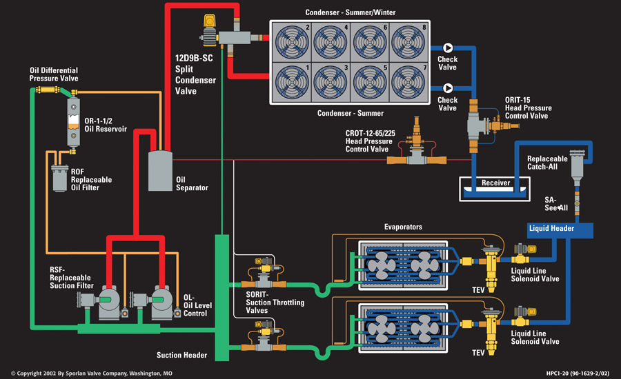
Larger receivers are needed for these systems to hold the extra refrigerant for condenser flooding in the summer months. While the condenser is being flooded with liquid refrigerant, a close on rise of outlet (CRO) valve located between the compressor’s discharge line and the receiver inlet will bypass hot compressor discharge gas to the receiver inlet when it senses a preset pressure difference between the discharge line and the receiver. The “T” shown in Figure 1 simply means the valve comes with a built-in pressure tap for ease of taking a pressure for service purposes and for setting the valve. The pressure difference is created from the reduced flow of refrigerant to the receiver because of the throttling action of the ORI valve. The bypassed hot gas through the CRO valve serves to warm up any cold liquid coming from the ORI valve at the receiver’s inlet, and it will also increase the pressure of the receiver, so metering devices will have the proper liquid-line pressure feeding them.
One of the main advantages of condenser flooding is to keep consistent liquid pressure feeding the metering device in low ambient conditions. Manufacturers supply technical information on how much extra refrigerant is needed for flooding a condenser for a certain low ambient condition. However, in extreme low ambient conditions, it may be necessary to flood 80-90 percent of the condenser. On larger systems, this could mean several hundred pounds of refrigerant. This is the main disadvantage of flooding a condenser for low ambient operations. With the rising price of refrigerant and the environmental concerns of global warming and ozone depletion, condenser flooding can become quite expensive and environmentally unsound if not managed and serviced properly.
CONDENSER SPLITTING
One way to reduce the amount of extra refrigerant charge needed for condenser flooding is to split the condenser into two separate and identical condenser circuits (see Figure 1). This method is referred to as condenser splitting. The splitting of the condensers is done with the addition of a pilot-operated, three-way solenoid valve installed in the discharge line from the compressors located after the oil separator. The splitting of the identical condensers is done in such a way where only one-half of the condenser is used for winter operation, and both halves are used for summer operation. The top half of the condenser is referred to as the “summer/winter” condenser, and the bottom half of the condenser is referred to as the “summer” condenser. The three-way solenoid valve controlling the splitting of the condensers can be energized and de-energized by a controller sensing outside ambient, an outdoor thermostat, or a high-side pressure control.
During summer operations, the added surface area and volume of both condensers are needed to maintain a reasonable head pressure at higher ambient conditions. The pilot-operated, three-way solenoid valve is then de-energized. This positions the main piston inside the valve to let refrigerant flow from the compressor’s discharge line to the three-way valve’s inlet port and then equally to the valve’s two outer ports. In other words, refrigerant will flow to both of the condenser halves equally.
In low ambient conditions, the summer portion of the condenser can be taken out of the active refrigeration system by the three-way valve. When the coil of the pilot-operated, three-way solenoid valve is energized, the sliding piston inside the valve will move and close off the flow of refrigerant to the port on the bottom of the valve that feeds the summer condenser. This action will render the summer condenser inactive or idle, and the minimum head pressure can be maintained by flooding the summer/winter half of the condenser with conventional refrigerant-side head-pressure control valves, as explained in the condenser flooding section of this article.
During winter operations, the system’s head pressure is best maintained with a combination of condenser-splitting, refrigerant-side head-pressure controls, and air-side controls, like fan cycling or fan variable-speed devices. This combination of refrigerant and air-side controls will minimize the refrigerant charge even more while splitting the condenser. These combinations will also maintain the correct head pressure for better system efficiencies.
The refrigerant that is trapped in the idle summer condenser during low ambient conditions will flow back into the active system through a bleed hole in the piston of the three-way valve. This trapped refrigerant will flow through the piston’s bleed hole, into the valve’s pilot assembly, and back to the suction header through a small copper line that feeds all parallel compressors (see Figure 1).
Another scheme to rid the idle summer condenser of its refrigerant is to have a dedicated pump-out solenoid valve that will open when energized and vent the trapped refrigerant to the common suction header through a capillary tube restriction. Both the bleed hole in the piston or the capillary tube ensure the refrigerant experiences a restriction and is mostly vaporized before reaching the common suction header, which is under low-side (common suction) pressure.
A check valve is located at the summer condenser’s outlet to prevent any refrigerant from entering it while it is idle and under a low-pressure condition. Although not needed for backflow prevention, a check valve is also located at the outlet of the summer/winter condenser simply to make sure the pressure drops equally in both halves of the condenser when both are being used simultaneously in summertime operations.
Publication date: 10/10/2016
Want more HVAC industry news and information? Join The NEWS on Facebook, Twitter, and LinkedIn today!


Report Abusive Comment