The popularity of geothermal heat pumps continues to grow. These days, you can read about them in just about every issue of every HVAC trade publication. They offer a way to provide low-cost heating as well as cooling.
An increasing number of state energy offices are formally recognizing geothermal heat pumps as renewable energy sources. This allows them to qualify for various financial incentive programs. Some electric utilities also are offering incentive programs to encourage their use. The federal government recognizes geothermal heat pumps that meet Energy Star requirements as eligible for a 30 percent Residential Renewable Energy Tax Credit through 2016.
Heat pumps also dovetail nicely with solar photovoltaic systems in buildings aiming for net-zero status. In locations where net metering is available, surplus electrical energy generated by the solar PV system can be sent back to the electric utility grid. The utility meter records this reverse energy flow. In effect, the surplus electrical energy is sold back to the utility at full retail cost. It can then be repurchased, when required.
This allows surplus solar-derived electrical energy to be stored on the electrical grid, perhaps for several months, and later drawn back through the building’s electrical meter without financial penalty. Thus, it’s possible for surplus solar-derived electrical energy, created during times when there is little if any operation of the heat pump, to be used by the heat pump during the cold and dark of winter. This is a very significant and synergistic benefit, one that will become increasingly common as the demand for net-zero buildings increases.
A bright future for electrically driven heat pumps is supported by increasing utility-scale power generation by large wind turbine farms and multi-megawatt arrays of solar PV panels.
HEAT PUMP HELPER
Although it’s possible to size a geothermal heat pump to provide the full design heating load of a house, there are other options. One alternative that lends itself to modern hydronics technology is to combine the heat pump with a boiler. This is often called a dual-fuel approach, and several benefits are associated with it.
For example, in some locations, utilities offer steeply discounted “time-of-use” electrical energy prices during periods of low demand. These rates can significantly reduce the operating cost of a heat pump during off-peak hours while allowing a gas-fired boiler to meet demand during peak periods, when electrical rates are significantly higher.
A dual-fuel system also provides the security that one heat source can cover some or all the heating load when the other heat source is down for maintenance.
Finally, a dual-fuel approach allows for the possibility of sizing the water-to-water geothermal heat pump to less than the design heating load of the building. This may be necessary due to limited land area for installation of the earth loop. It also may be necessary in situations where earth-loop installation costs are high.
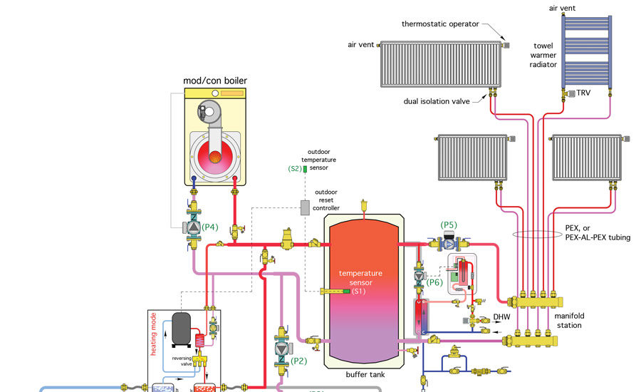
The schematic in Figure 2 shows one way to combine a water-to-water geothermal heat pump with a propane-fired mod/con boiler. This combisystem provides heating, cooling, and domestic hot water.
A valved manifold station serves as the beginning and ending point for all parallel earth loop branches. The earth-loop circuit has an expansion tank as well as a combined air and dirt separator. Flow through the earth loop is provided by a single electronically commutated motor (ECM)-based circulator, which operates whenever the heat pump’s compressor is on. This circulator can operate in fixed-speed mode or in a variable-speed mode, if a suitable controller is provided that can optimize earth-loop flow rate for a given operating condition.
The buffer tank receives heat from the heat pump as well as the propane-fired boiler. This tank prevents either heat source from short-cycling. It allows both heat sources to operate simultaneously, if necessary, under high-demand situations. The buffer tank also provides hydraulic separation between the various circulators used in the system.
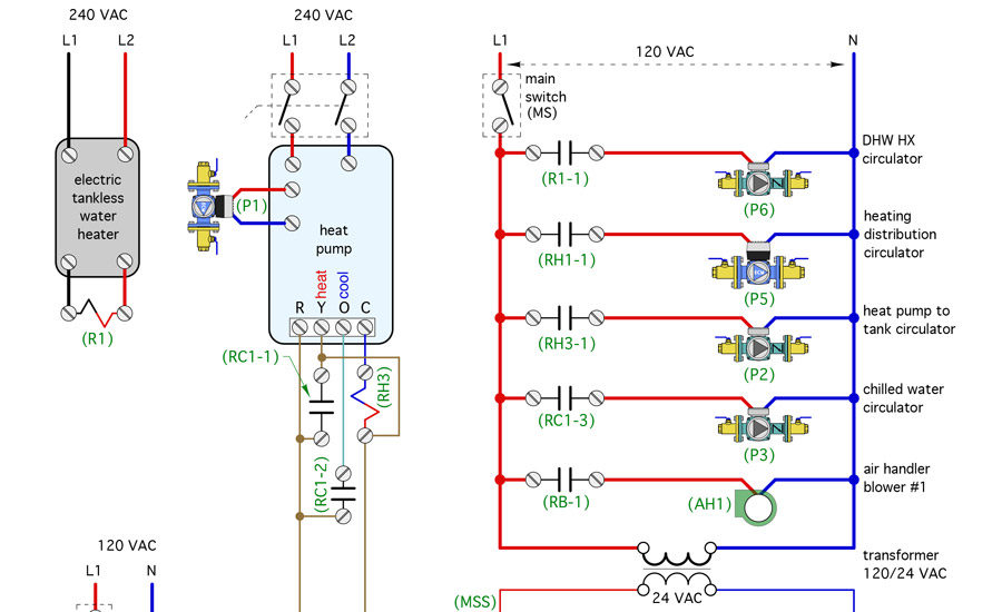
Domestic water is heated on demand using an external stainless steel, brazed-plate heat exchanger. Whenever there is a demand for domestic hot water of 0.6 gpm or higher, the flow switch inside the tankless electric water heater closes. This closure is used in combination with a relay to turn on circulator (P6), which moves water from the upper portion of the buffer tank through the primary side of this heat exchanger.
Closure of the flow switch energizes a contactor within the tankless heater that supplies 240 vac to the heating elements. The electrical current supplied to these elements is regulated through solid-state devices called triacs, which are under the control of a microprocessor within the tankless heater. The power delivered is limited to that required to provide any necessary temperature boost between the preheated water leaving the brazed-plate heat exchanger and the desired domestic hot water delivery temperature. All heated water leaving the tankless heater flows into a thermostatic mixing valve to ensure a safe delivery temperature to the fixtures.
DESUPERHEATING DETAILS
The desuperheater heat exchanger within the heat pump also adds heat to the buffer tank whenever the compressor is operating. This heat can be used for space heating or by the on-demand domestic water heating subsystem. When the heat pump is operating in cooling mode, the heat transferred to the buffer tank by the desuperheater is truly free heat that otherwise would be dissipated to the earth loop. This allows the earth loop to operate at slightly lower fluid temperatures, which improves the EER of the heat pump.
When the heat pump operates in heating mode, heat is transferred from the refrigerant to system water through the condenser as well as the desuperheater. This slightly increases the heat pump’s coefficiency of performance when compared to its normal mode of operation in which only the condenser is removing heat from the refrigerant.
The space-heating distribution system uses panel radiators that are sized to operate at supply water temperatures of 120°F at design load conditions. Each panel radiator is equipped with a thermostatic radiator valve that allows room-by-room temperature adjustment. All panel radiators are supplied through a homerun distribution system using ½-inch PEX or PEX-AL-PEX tubing from a common manifold station.
Flow is created by a variable-speed, pressure-regulated circulator set for constant differential pressure operation. For simplicity, only four radiators are shown in Figure 2. However, a larger manifold could be used to expand the distribution system to supply several more radiators.
Under partial-load conditions, the water temperature required for space heating decreases based on outdoor reset control. At 50 percent load, the water temperature supplied to the panel radiators only needs to be about 95°. This significantly improves the coefficient of performance (COP) of the heat pump and the mod/con boiler, if it is used.
Operation of the space-heating distribution circulator (P5) is controlled by the master thermostat (T1). If this thermostat is satisfied, circulator (P5) is turned off and no heat flows to the distribution system. This allows the entire building to be put into a reduced temperature setback mode from a single thermostat. During the heating season, the setting of the master thermostat should be 2° or 3° above the normal desired air temperature. This maintains circulator (P5) in operation and allows the individual thermostatic radiator valves to fine tune the comfort level in their respective spaces.
CHILLING OUT
Cooling is provided by a single chilled-water air handler matched to the cooling capacity of the heat pump. Thus, no buffer tank is required in cooling-mode operation. The air handler is equipped with a drip pan and drain to dispose of condensate that forms on its coil. All portions of the piping system that handle chilled water are insulated and vapor-sealed to prevent condensation. An electrical schematic for this system is shown in Figure 1.
During heating mode operation, a two-stage outdoor reset controller provides the logic that favors use of the geothermal heat pump when possible, but also invokes the boiler, when necessary. If the output from the heat pump is sufficient to keep the buffer tank temperature at or close to the target supply water temperature, the boiler will not operate. However, if heat output from the heat pump cannot keep pace with heat removal from the buffer tank, the boiler will be turned on as the second-stage heat source. In this scenario, both the heat pump and boiler can simultaneously add heat to the buffer tank.
The blower in the air handler will always operate in cooling mode. It also can operate in heating mode if the fan switch on thermostat (T1) is set to “on.” If the blower is not to run during the heating mode, switch (SW1) should be closed. This allows 24 vac to energize the coil of relay (RO), when thermostat (T1) calls for heat. A normally closed contact (RO-1) opens, interrupting 24 vac to the blower relay (RB) and thus preventing the blower from operating. If switch (SW1) is left open, the blower will operate whenever thermostat (T1) calls for heating.
This system demonstrates how modern hydronics technology can be used to harmonize the operation of two high-efficiency heat sources — one renewable and the other conventional. It uses state-of-the-art hardware to maximize the efficiency of both heat sources, deliver room-by-room comfort control in heating, whole-house cooling, and provide on-demand domestic hot water. This system is sophisticated, but not overly complicated. Perhaps you can find a building in which to apply it.
Publication date: 5/30/2016
Want more HVAC industry news and information? Join The NEWS on Facebook, Twitter, and LinkedIn today!


Report Abusive Comment