|
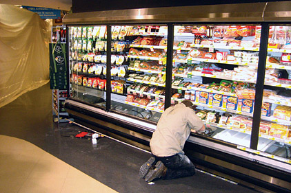
| A service technician makes an expansion valve adjustment. |
If performed properly, retrofits of open cases with glass doors will lead to sizable reductions in infiltration loads, reducing overall case heat loads by 50-80 percent as compared to the original open case performance, according to laboratory studies and experts interviewed during the development of this guide. Additional system improvements performed concurrently, such as upgrading fan motors, installing higher-efficiency lighting, and raising case saturated evaporator temperatures, can further reduce the heat load from the refrigerated display case.
In light of these substantial reductions in refrigeration load, it is imperative that the refrigeration system configuration be reevaluated to match system operation to the load profile. According to experts interviewed, improper reconfiguration of refrigeration systems is the predominant cause of case retrofit projects not delivering the expected results. The following sections outline guidance for properly reconfiguring refrigeration systems after retrofitting open cases with doors.
Load-Profile Evaluation
The first step in properly reconfiguring the refrigeration system should consist of a thorough analysis of the load profile for the retrofit cases. Ideally, such system analysis would have been performed as part of the initial engineering assessment in the preplanning phase of the retrofit.
Perform a detailed analysis that accounts for periods of maximum customer traffic and adverse ambient conditions. Maximum heat load estimates will be necessary to ensure that the reconfigured refrigeration system is still capable of delivering the needed cooling capacity under the most extreme conditions that it will encounter so as to ensure product freshness and food safety.
Refrigerant Reclamation
When working with the sealed refrigeration system, it is imperative that refrigerant leaks be prevented. Before any work requiring opening of the sealed system or which could result in accidental puncture of the system is performed, refrigerant should be evacuated from the affected portions of the system or systems per the applicable federal, state, and other regulations. Refrigerant evacuated from the system should be retained or recycled per the appropriate guidelines.
Compressor Rack and Control Configuration
Proper modification of the compressor rack and adjustment of refrigeration system controls constitutes one of the most significant and important aspects of the retrofit process. Installation of doors on open cases, which are traditionally the largest contributors to the refrigeration system heat load, will result in markedly different operating conditions for the compressor rack serving those cases. Failure to properly configure the rack to best match the case load profile will result in a mismatch between the load steps of the rack and the actual loads from the cases, resulting in excessive compressor cycling. This mode of operation is much less efficient than the higher-duty cycle operation typically observed when the refrigeration system is well matched to the load. Moreover, the added stress of starting and stopping the moving components through many additional cycles can lead to excessive wear and tear on the compressor rack, resulting in shortened operational life and additional repair costs.
In addition to performing any necessary modifications to the compressor rack and controls to accommodate the new refrigeration load, the refrigeration contractor should take this opportunity to thoroughly inspect the rack and related equipment for any existing damage or wear and perform the necessary maintenance or repairs to ensure peak performance. Standard maintenance checks of the compressors, in accordance with the recommendations of the compressor manufacturer, should be performed.
The contractor coordinating the retrofit operation should examine the following areas related to the compressor rack and refrigeration system controls.
Compressor Rack Configuration
In many cases, the decreased load on the compressor rack due to the addition of display doors to open cases will necessitate physical changes to the rack in order to accommodate the modified refrigerant throughput and characteristics. Results of calculations of the case heat load under various sets of operating conditions, performed prior to case retrofit operations, should be the key driver for changes to the rack configuration.
In many cases, the reduction in peak heat load seen by the rack will be significant enough to warrant the disabling of one or more compressors on the rack. In this instance, care should be taken to ensure that the rack remains configured in a manner so as to provide appropriate capacity modulation in order to mitigate excessive compressor cycling and product temperature fluctuations. For example, on a rack with differently sized parallel compressors, it may be desirable to disable the larger compressors first, while leaving the smaller ones in place to allow for more granularities in load control. Load steps should be compared against anticipated heat load increments, and further compressor changes may be required if the disparity is significant.
In addition to potential reconfiguration of the compressors themselves, additional modifications may need to be made to the following rack components to ensure optimal performance:
• Oil return: Attention should be paid to the suction risers in ensuring proper oil return. If the risers are not properly sized, the rate of lubricant return may be insufficient and damage to the compressors could occur. In many cases, the existing risers will be sufficient. However, the engineer overseeing the project should verify that this is the case in order to maintain proper performance. If warranted, changes to the risers should be made based on the type of system, depending on whether it is a split-tube design, features a siphon in the riser, or uses an oil separation system. After the retrofit, the operator or contractor should observe oil levels in the separator, reservoir, and/or crankcase to ensure that proper oil return is occurring.
• Refrigerant charge: Charge level should be checked at the receiver and adjusted to ensure agreement between the level of charge and the system’s needs after the retrofit.
• Receivers: Standard maintenance checks should be performed.
Controls and Calibration
After the necessary physical alterations to the compressor rack are made, existing control systems should be recalibrated to ensure proper performance. Additionally, building owners could use the retrofit project as an opportunity to upgrade existing controls with more advanced systems. Controls that should be examined by the refrigeration engineer or firm responsible for the retrofit include:
• Variable-frequency drive (VFD) systems;
• Cylinder unloading;
• Building energy management systems (EMS);
• Defrost control systems; and
• Other control systems and schemes.
Hot Gas Defrost
If the rack is equipped with the capacity to accommodate hot gas defrosting of coils, the solenoid valve on the main liquid line or the discharge differential valves should be evaluated for compatibility with the new system operating parameters and replaced if necessary.
Heat Reclaim
If the rack contains the capacity to perform heat reclaim, calculations should be performed to evaluate the new heat output of the rack when operating in conjunction with the newly retrofitted cases. With reduced heat output, the existing heat reclaim coil could potentially prove to be oversized. If changes to the compressors have been made, this is likely.
Refrigerant Piping and Expansion Valves
The significant decrease in refrigeration load due to the addition of doors on cases has the potential to affect many components of the refrigeration system, including the refrigerant line runs and the case expansion valves. Generally, experts who provided input for this guide stated that liquid and suction lines will both remain appropriate in size to serve the retrofitted cases. However, some sources stated that attention should be paid to the suction riser (the line running from the evaporator coil outlet to the shared suction line on top of the lineup) in order to ensure adequate refrigerant velocity, and thus proper oil return. The engineer coordinating the case retrofit should conduct sufficiently detailed system modeling and flow calculations to ensure that the line sizes utilized will be capable of properly returning a sufficient capacity of refrigerant and lubricant while maintaining the desired properties. Minimum ASHRAE design considerations, including a minimum suction line velocity of 500 feet per minute and a minimum suction riser velocity of 1,000 feet per minute, should be followed.
Expansion valves attached to each individual coil in the display cases serve the critical function of controlling coil superheat, and will require changes to accommodate the markedly different refrigerant flow properties precipitated by the change in the case configuration during the retrofit. For expansion valves with removable internal cartridges, a compatible cartridge properly sized for the new refrigerant flow level may be available. In other instances, expansion valves will need to be replaced altogether. During system analysis and modeling, the engineer supervising the retrofit should analyze the anticipated heat loads and refrigerant flow conditions, and choose properly sized valves for each display case accordingly. Industry experts stated that expansion valves will likely need to be reduced one or two sizes to provide for proper superheat control at reduced refrigerant flow rates and increased evaporator temperatures. The suggested superheat recommended to DOE was 4-7°; however, the case equipment manufacturer’s literature should be consulted to verify.
If electronic expansion valves are in place, generally the valves will not need to be altered. However, the valve manufacturer’s literature should be reviewed in order to ensure the valves’ compatibility with the new system configuration.
Additionally, each case lineup contains a solenoid valve or electronic pressure regulator (EPR) used to control case temperature. Solenoid valves used in either the liquid or suction lines can generally be retained, provided that the sizing of the lines is evaluated as described above to ensure a proper operating pressure across the valve. However, due to the fact that the reduction in load created by the retrofit allows for higher case suction temperatures, an EPR is preferred for optimal performance. Existing EPRs should be checked for proper performance at the new case loads. If possible, the common suction temperature downstream of the EPR should be raised in order to further reduce the power input requirement at the compressor rack.
Condensers
Supermarket refrigeration systems generally use separate air-cooled condensers, most often located on the rooftop of the building, to reject heat to the ambient environment. In many cases, excess condenser capacity will already be accounted for by existing control and operation schemes. However, in some instances, removal of excess condenser capacity may be warranted. Additionally, operators in climates experiencing extreme winter cold or high summer temperatures should consider climatic factors when making modifications to their condensers.
Discharge Risers
The discharge riser (the piping from the compressor rack outlet to the condenser) should be evaluated for proper sizing based upon the new system operating parameters. In many cases, the existing sizing will be adequate. However, if the retrofits were significant enough to create a sufficient impact on the given system, the line may need to be resized in order to ensure sufficient lubricant return to the compressor rack.
Winter Control
Some condensers may be equipped with a device, known as winter control, which regulates the head pressure to prevent it from falling below optimal condensing pressure during low ambient temperature conditions. If the condenser has the capacity for winter control and there is a sufficiently significant reduction of case heat load (a figure of 35-40 percent was suggested as a guideline), the winter control valve should be checked and resized if necessary.
Subcooling
If the condenser features subcooling and the drop in case heat load is sufficient (a figure of 35 to 40 percent was suggested as a guideline), the subcooler and the associated expansion valves may need to be resized.
Unitary Condensing Units
In systems featuring unitary condensing units, with a single display case being served by a dedicated remote condenser, the issue of load reduction is likely to have a more pronounced impact than in multiplex rack systems. This is due to the fact that the single condensing unit operates on demand based solely on the conditions in the case served, and is originally sized to the anticipated load of the case. Whereas a rack system often can be modified in a fairly straightforward manner to accommodate lower case loads (such as through disconnecting a compressor or adjusting existing controls), this may not be possible using the existing equipment in a dedicated remote-condensing unit. If the unit is left to run as is with a case load that is 50 percent or more below that for which it was originally designed, the condensing unit will be grossly oversized, and the result will be frequent compressor cycling. This will result in highly inefficient operation due to the high number of compressor and condenser fan starts and stops, as well as possible shortening of refrigerated product lifetime due to rapid warming and cooling cycles.
In light of the resulting discrepancy between case heat load and condensing unit capacity after a retrofit, one of two measures could be employed in order to bring the two values closer into line. The first of these would be the employment of an electronic suction regulator or similar control device to hold the refrigerant flow so that the condensing unit experiences a reduced impact due to the decrease in load. However, since this step enables the condensing unit to operate in a manner similar to which it did with an open case, this means that the full energy savings will not be realized. Another measure, if feasible based on the physical size and location of the cases, is the consolidation of multiple cases onto single condensing units. In this instance, a unitary condensing unit which originally served a single display case could be reconfigured to serve two cases through rerouting of refrigerant piping and other adjustments. Proper calculations should be carried out in order to ensure that the existing condensing unit is capable of accommodating the peak loads of multiple cases.
Electrical System
Retrofit operations, by design, have the intended result of significantly changing the electrical demand profiles of the display cases and refrigeration systems. Case electrical consumption may be reduced due to changes in lighting and fan power, while a compressor rack reconfigured for retrofitted cases may use, even in peak operation, far less electricity than it previously needed. While this is desirable from an energy-efficiency and cost-reduction standpoint, care must be taken to ensure that the building electrical system is still correctly sized for the refrigeration equipment per the relevant building and safety codes. For example, existing circuit breakers may be grossly oversized and may not trip even in the case of an overload situation, which could present a serious safety hazard. A qualified engineer or firm should be consulted to ensure that all building codes and electrical safety requirements are met, and that the building electricity supply and connections are properly sized for the new operating profile of the system. Display cases and refrigeration systems are generally labeled in a manner that reflects the necessary certification of the equipment, usually UL and NSF for the former and UL for the latter. Changes to the physical composition of the cases by way of component swaps and additions, as well as changes to the case electrical system, would likely require recertification with these bodies. Similarly, any changes to the components of the rack may require recertification.
System Recharging
Any work to the sealed portion of the refrigeration system will have required evacuation of the refrigerant in the system previous to the modifications being performed. Prior to restarting the system, the refrigeration contractor should ensure that those portions which have been evacuated are properly recharged to the necessary levels using the appropriate refrigerant. Particular attention should be paid to any system modifications that could result in a change in the needed refrigerant charge. For example, due to the load reductions on the system, each case’s evaporator coil may require an increased charge, resulting in a need to add more refrigerant to the entirety of the system before it is returned to service.
EDITOR’S NOTE: This work was accomplished with the guidance of Brian Holuj, Jason Koman, and Kristen Taddonio of the DOE, and through the contributions of many Better Building Alliance (BBA) members and representatives of industry. The DOE wishes to particularly acknowledge the efforts of the following parties: DC Engineering, Hillphoenix, Hussmann Corp., REMIS America LLC and REMIS GmbH, and Zero Zone Inc.
This report should be viewed as a general guide to best practices and factors for consideration by end users who are planning or evaluating a retrofit operation, rather than a comprehensive and exhaustive set of specific steps to perform when retrofitting display cases. A qualified refrigeration engineer or firm should always be contracted to oversee any retrofit project. This report was prepared as an account of work sponsored by an agency of the United States government. Neither the United States government, nor any agency thereof, nor any of their employees, nor any of their contractors, subcontractors, or their employees, makes any warranty, express or implied, or assumes any legal liability or responsibility for the accuracy, completeness, or usefulness of any information, apparatus, product, or process disclosed, or represents that its use would not infringe privately owned rights. Reference herein to any specific commercial product, process, or service by trade name, trademark, manufacturer, or otherwise, does not necessarily constitute or imply its endorsement, recommendation, or favoring by the United States government or any agency, contractor, or subcontractor thereof.
Publication date: 7/15/2013

Report Abusive Comment