Bob and Btu Buddy have gotten together for a review of their last service call, which involved a control system that Bob was not very familiar with - pneumatic controls.
Bob asked, “Why would anyone want to use air as the power source to operate the controls for a building?”
Btu Buddy said, “There are several reasons that pneumatic controls are desirable:
1.They are considered a mechanical type control that is basic enough that most anyone can become familiar with them and perform service on them. No electrical or electronic background is needed. In the past, plumbers did much of the work on installations of HVAC equipment. Installing pneumatic controls is running piping to move the air in the control system to the correct places.
2.Controls were designed that would provide proportioning of hot and chilled water to the various parts of an HVAC system with pneumatic controls. This was years before electronic controls. In the past, the system would just start and run until the thermostat called for the system to stop. This start and then stop caused temperature swings in the conditioned space. As we have talked about before, it would be much like having a start and stop switch on the fuel to a car. The throttle or accelerator in the car provides proportional fuel control and gives the driver more even control.
3.Most of the pneumatic controls were run with copper tubing which is very durable and strong. The control system would last for years in an office building or industrial plant. Plastic tubing is common today.
4.There is no fire hazard or electrical hazard with pneumatic controls. This is very desirable in many industrial applications. Where explosion or fire hazard is likely, such as petroleum plants or textile mills, electrical wiring must be installed in explosion proof piping and boxes. This is very expensive.
5.Pneumatic controls are very reliable.”
Bob said, “I really didn’t think about all of those things.”
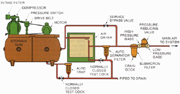
Figure 1. This is a basic pneumatic control system refrigerated air supply. (Figures are from Refrigeration & Air Conditioning Technology, 5th Edition, by William Whitman, William Johnson, and John Tomczyk, published by Delmar Cengage Learning.) (©Delmar Cengage Learning.) (Click on the image for an enlarged view.)
The air in the tank is stored at about 100 psig. This pressure is much too high for the controls to operate with, so the clean, dry 100 psig air leaving the storage container is reduced to about 20 psig for the operating pressure for the system.
The system is basically made up of control devices and controlled devices. The control device may be a temperature control, pressure control, flow control, or many other devices that may be used to control systems. The controlled devices are valves, dampers, motor speeds, or any other device that may need controlling.

Figure 2. This is a typical air operated cylinder for a pneumatic control system. (©Delmar Cengage Learning.) (Click on the image for an enlarged view.)
Bob said, “This is all sounding very practical, up to now. How does a simple system work?”
Btu Buddy explained, “Let’s look at this air operated cylinder (Figure 3). This cylinder operates a valve in the water line. The example shows the thermostat set at 75°F. The thermostat is set to pass 7½ psig of air to the air cylinder. The cylinder is in the mid-position. Suppose there is a decrease in room temperature to 72°; the room thermostat may reduce the air pressure to the cylinder to 5 psig and the cylinder piston would move to a new position and change the valve in the water line to fully bypass the water around the coil, and there would be no cooling. The return air would be returned to the room with no cooling.

Figure 3. This is a typical chilled water coil with a pneumatically controlled valve that will allow water to be either full flow or bypassed or any value in between. This is the type of valve that must be used for a chilled water system to ensure the same water flow through the system at all times. Constant water flow must be maintained through the chiller. (©Delmar Cengage Learning.) (Click on the image for an enlarged view.)
There is a little bit more that should be added. Notice the little box attached to the air cylinder. It has a spring attached to the air cylinder to measure the travel of the cylinder shaft. It is called a pilot positioner. Also notice that there are two different line sizes in the system, 3/8 inch and ¼ inch. As mentioned before, the port size in the controls is really small, too small to fill the air cylinder with enough air to act quickly. That is the purpose of the pilot positioner. The main line, 3/8 inch, is fed to the pilot positioner and then on to the air cylinder. The pilot positioner actually governs main line air to the air cylinder and the thermostat tells the pilot positioner when to feed large volume flow to the large volume air cylinder.”
Bob then said, “These controls seem simple. Where would I learn more about them?”
Btu Buddy said, “The best thing a technician could do to learn more about these controls is to work alongside an experienced control technician.”
“Well,” said Bob, “I know one of those. I guess I need to talk to him and see if he will give me some hands-on training.”
Btu Buddy said, “A good technician would be glad to share his skills with you.”
Publication date:12/20/2010


Report Abusive Comment